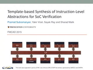
Introduction to Digital Logic Abstractions and Gates
Explore the world of digital logic through abstractions in computer science, focusing on basic gates like Inverter, NAND, AND, OR, XOR, and more. Learn about logic blocks, adders, and half-adders, and understand how logical functions are constructed using fundamental logic gates. Discover the implementation of various gates and their truth tables in building complex logical systems.

Download Presentation

Please find below an Image/Link to download the presentation.
The content on the website is provided AS IS for your information and personal use only. It may not be sold, licensed, or shared on other websites without obtaining consent from the author.If you encounter any issues during the download, it is possible that the publisher has removed the file from their server.
You are allowed to download the files provided on this website for personal or commercial use, subject to the condition that they are used lawfully. All files are the property of their respective owners.
The content on the website is provided AS IS for your information and personal use only. It may not be sold, licensed, or shared on other websites without obtaining consent from the author.
E N D
Presentation Transcript
Abstractions in CS (gates) Basic Gate: Inverter Truth Table I 0 1 O 1 0 I O GND I O Resister (limits conductivity) Vcc 2
Abstractions in CS (gates) Truth Table I 0 1 O 1 0 I O 3
Abstractions in CS (gates) Basic Gate: NAND (Negated AND) Truth Table A B A B 0 0 1 1 Y Y 0 1 0 1 1 1 1 0 GND A B Y Vcc 4
Abstractions in CS (gates) Basic Gate: AND Truth Table A B 0 0 1 1 Y 0 1 0 1 0 0 0 1 A B Y 5
Abstractions in CS (gates) Other Basic Gates: OR gate Truth Table A B 0 0 1 1 Y 0 1 0 1 0 1 1 1 A B Y 6
Abstractions in CS (gates) Other Basic Gates: XOR gate Truth Table A B 0 0 1 1 Y 0 1 0 1 0 1 1 0 A B Y 7
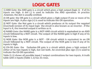
Logic Blocks Logic blocks are built from gates that implement basic logic functions Any logical function can be constructed using AND gates, OR gates, and inversion. 8
Adder In computers, the most common task is add. In MIPS, we write add $t0, $t1, $t2. The hardware will get the values of $t1 and $t2, feed them to an adder, and store the result back to $t0. So how the adder is implemented?
Half-adder How to implement a half-adder with logic gates? A half adder takes two inputs, a and b, and generates two outputs, sum and carry. The inputs and outputs are all one-bit values. a sum b carry
Half-adder First, how many possible combinations of inputs?
Half-adder Four combinations. a b sum carry 0 0 0 1 1 0 1 1
Half-adder The value of sum should be? Carry? a b sum carry 0 0 0 1 1 0 1 1
Half-adder Okay. We have two outputs. But let s implement them one by one. First, how to get sum? Hint: look at the truth table. a b sum 0 0 0 0 1 1 1 0 1 1 1 0
Half-adder Sum a b sum
How about carry? The truth table is a b carry 0 0 0 0 1 0 1 0 0 1 1 1
Carry So, the circuit for carry is a b carry
Half-adder Put them together, we get a b sum carry
1-Bit Adder 1-bit full adder Also called a (3, 2) adder 19
Sum? Sum is `1 when one of the following four cases is true: a=1, b=0, c=0 a=0, b=1, c=0 a=0, b=0, c=1 a=1, b=1, c=1
Sum The idea is that we will build a circuit made of and gates and or gate faithfully according to the truth table. Each and gate corresponds to one ``true row in the truth table. The and gate should output a ```1 if and only if the input combination is the same as this row. If all other cases, the output is ``0. So, whenever the input combination falls in one of the ``true rows, one of the and gates is ``1 , so the output of the or gate is 1. If the input combination does not fall into any of the ``true rows, none of the and gates will output a ``1 , so the output of the or gate is 0.
Boolean Algebra We express logic functions using logic equations using Boolean algebra The OR operator is written as +, as in A + B. The AND operator is written as , as A B. The unary operator NOT is written as . or A . Remember: This is not the binary field. Here 0+0=0, 0+1=1+0=1, 1+1=1. 24
Carryout bit? Carryout bit is 1 also on four cases. When a, b and carryin are 110, 101, 011, 111. Does it mean that we need a similar circuit as sum?
Carryout bit Actually, it can be simpler
Delay Hardware has delays. Delay is defined as the time since the input is stable to the time when the output is stable. How much delay do you think the one-bit half adder is and the one-bit full adder is?
1-Bit Adder 29
32-bit adder How to get the 32-bit adder used in MIPS?

")
")
")
")
")
")