Introduction to Latches and Flip-Flops
This content covers the basics of latches and flip-flops in digital electronics. Explore the concepts of S-R and gated D latches, flip-flops, characteristic equations, timing diagrams, construction analysis using gates, and more. Understand the difference between combinational and sequential logic circuits, memory circuits, and feedback circuits. Dive into the operation of Set-Reset (S-R) latches with detailed diagrams illustrating their functions and characteristics.

Download Presentation

Please find below an Image/Link to download the presentation.
The content on the website is provided AS IS for your information and personal use only. It may not be sold, licensed, or shared on other websites without obtaining consent from the author.If you encounter any issues during the download, it is possible that the publisher has removed the file from their server.
You are allowed to download the files provided on this website for personal or commercial use, subject to the condition that they are used lawfully. All files are the property of their respective owners.
The content on the website is provided AS IS for your information and personal use only. It may not be sold, licensed, or shared on other websites without obtaining consent from the author.
E N D
Presentation Transcript
I 6 Apr., 05, 2021
Part 1 Latches
Objectives 1. S-R and gated D latches 2. D, D-CE, S-R, J-K and T flip-flops 3. Characteristic (next-state) equations 4. Timing diagram 5. Construction analysis of latches and flip-flops using gates
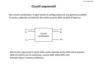
Introduction Logic Circuit Combinational logic circuit Sequential logic circuit: output depends on Present input Past sequence of inputs Memory circuit Feedback circuit
Introduction An Inverter with Feedback Unstable state Two Inverters with Feedback Stable state
Set-Reset Latch Simple Latch Two stable states and has memory function S = R = 0 Q = 0 S = 1, R = 0 Q = 1 P 1 P 0 Q 1 Q 0 S S 0 1 0 R 0 R (b) (a) S = R = 0 Q = 1 S = 0, R = 1 Q = 0 P 1 P 0 Q 1 Q 0 0 S 0 S 0 R (c) 1 R (d)
Set-Reset Latch S-R Latch S: Sets the output to Q=1 R: Resets the output to Q=0 S=R=1 is not allowed Cross-coupled Form Symbol Q Q Q Q R S R S
Set-Reset Latch Improper S-R Latch Operation (S = R = 1 is prohibited) 1 0 S P 0 1 0 1 0 1 0 1 Q R 1 0 If S = R = 1, then It violates the basic rule of latch operation. It oscillates.
Set-Reset Latch Timing Diagram for S-R Latch : response time or delay time S R Q
Set-Reset Latch S-R Latch Operation S(t) R(t) Q(t) Q(t+ ) Q(t): Present state 0 0 0 0 0 1 0 1 0 0 1 1 1 0 0 1 0 1 1 1 0 1 1 1 0 1 0 0 1 1 - - Q(t+ ): Next state Inputs not allowed
Set-Reset Latch Characteristic Equation for S-R Latch 0 1 S(t) R(t) Q(t) Q(t+ ) 00 0 0 0 0 0 1 0 1 0 0 1 1 1 0 0 1 0 1 1 1 0 1 1 1 0 1 0 0 1 1 - - 01 11 ?+= ? + ? ? ?? = 0 10
Set-Reset Latch Application of an S-R Latch Switch Debouncing with an S-R Latch S S b +V 1 R a Q Q R
Set-Reset Latch Alternative Form of the S-R Latch Using NAND Gates: Latch ? ? S(t) R(t) Q(t) Q(t+ ) ? 1 1 0 1 1 1 1 0 0 1 0 1 0 1 0 0 1 1 0 0 0 0 0 1 0 1 0 0 1 1 - - ? S ? ? R ? ? ? ?
Gated D Latch Gated D Latch ? ? ? ? ? ? Transparent Latch ? ? ?
Gated D Latch Symbol and Truth Table for Gated D Latch G D Q Q+ ? ? 0 0 0 0 0 1 0 1 0 0 1 1 1 0 0 1 0 1 1 1 0 1 1 1 0 1 0 1 0 0 1 1 ? ? 00 01 11 10 0 1
Part 2 Flip-Flops
Edge-Triggered D Flip-Flop Flip-Flop Output changes only in response to the clock Rising-edge (positive-edge) Triggered Flip-Flop Output changes in response to a 0 to 1 transition on the clock Falling-edge (negative-edge) Triggered Flip-Flop Output changes in response to a 1 to 0 transition on the clock Active Edge Clock edge (rising or falling) that triggers the flip-flop
Edge-Triggered D Flip-Flop D Flip-Flops D Q Q+ 0 0 0 1 1 0 1 1 0 0 1 1 ? ? ? ? ?+= ? ?? ?? ? ? Truth table Timing for D Flip-Flop (Falling-Edge Trigger) ? ?? ?
Edge-Triggered D Flip-Flop D Flip-Flop (Rising-Edge Trigger) ? ? ? CLK CLK=?2 ?1 ? ? ?
Edge-Triggered D Flip-Flop Setup and Hold Times for an Edge-Triggered D Flip-Flop ? CLK ? ???:setup time ? :hold time ??:propagation delay
S-R Flip-Flop S-R Flip-Flop ? ? Ck ? ? Operation Summary S=R=0 S=1, R=0 S=0, R=1 S=R=1 no state change set Q to 1 (after active Ck edge) reset Q to 0 (after active Ck edge) not allowed
J-K Flip-Flop J-K Flip-Flop (Rising Edge Trigger Type) Q+ 0 1 0 0 1 1 1 0 J K Q 0 0 0 0 0 1 0 1 0 0 1 1 1 0 0 1 0 1 1 1 0 1 1 1 ? ? CK ? ? ?+= ?? + ? ? Next state table and characteristic equation
J-K Flip-Flop J-K Flip-Flop (Timing Chart) Q+ 0 1 0 0 1 1 1 0 J K Q 0 0 0 0 0 1 0 1 0 0 1 1 1 0 0 1 0 1 1 1 0 1 1 1 Clock ? ? ?
J-K Flip-Flop Master-Slave J-K Flip-Flop (Rising Edge Trigger Type) ? ? CLK ? ?
T Flip-Flop T Flip-Flop Q+ T Q 0 0 0 1 1 0 1 1 0 1 1 0 ? ? ?+= ? ? + ?? = ? ? Ck ?
T Flip-Flop Timing Diagram for T Flip-Flop (Falling-Edge Trigger) Q+ T Q 0 0 0 1 1 0 1 1 0 1 1 0 ? ? Ck ? Ck ? ?
T Flip-Flop Implementation of T Flip-Flop ? ? ? ? Ck Ck ? ? ? ? Clock Clock ?+= ?? + ? ? = ?? + ? ? ?
Flip-Flops with Additional Inputs D Flip-Flop with Asynchronous Clear and Preset Inputs Ck D PreN ClrN Q+ (not allowed) 1 0 0 1 Q(no charge) x x x x x x 0,1, 0 0 0 1 1 0 ? ? PreN ClrN ?? ? 0 1 1 1 1 1 x 1 1
Flip-Flops with Additional Inputs Timing Diagram for D Flip-Flop with Asynchronous Clear and Preset ? ? ClrN PreN ?? ? CLK ? ClrN PreN ?
Flip-Flops with Additional Inputs D Flip-Flop with Clock Enable 1 0 ? ? ? ? ? ? ??? CE CE CLK En Ck CLK Ck ? ? ? Ck (may result in loss of synchronization) (ideal synchronization) The characteristic equation : ?+= ? ?? + ? ?? The MUX output : ?+= ? = ? ?? + ??? ??
Summary Characteristic Equations (S-R latch or flip-flop) ?+= ? + ? ? ?? = 0 (gated D latch) ?+= ?? + ? ? ?+= ? (D flip-flop) ?+= ? ?? + ? ?? (D-CE flip-flop) ?+= ?? + ? ? (J-K flip-flop) (T flip-flop) ?+= ? ? = ? ? + ??