Introduction to Microprocessor and Microcontroller
A digital computer processes binary data using components like CPU, ALU, and memory. Explore the evolution of microprocessors from first to fifth generation, revolutionizing computer systems.

Download Presentation

Please find below an Image/Link to download the presentation.
The content on the website is provided AS IS for your information and personal use only. It may not be sold, licensed, or shared on other websites without obtaining consent from the author.If you encounter any issues during the download, it is possible that the publisher has removed the file from their server.
You are allowed to download the files provided on this website for personal or commercial use, subject to the condition that they are used lawfully. All files are the property of their respective owners.
The content on the website is provided AS IS for your information and personal use only. It may not be sold, licensed, or shared on other websites without obtaining consent from the author.
E N D
Presentation Transcript
MICROPROCESSOR AND MICROCONTROLLER UNIT-1 2/23/2025 1
Introduction Digital computer: A programmable machine that processes binary data is called digital computer. It is traditionally represented by five components CPU (central processing unit), ALU (arithmetic logic unit) and Control unit, memory, input and output. Traditional block diagram of a computer and microprocessor are presented in Fig.1 and Fig.2 respectively. 2/23/2025 2
Microprocessor as a CPU (MPU) With advent of integrated circuit technology, it became possible to build the CPU on a single chip, this came to be known as a microprocessor and the traditional block diagram is shown in fig.2 2/23/2025 4
Microprocessor Definition 1 It is a semiconductor device manufactured using the VLSI technique. It includes the ALU, register arrays and control units on a single chip. Definition 2 It is a program controlled device, which fetches (from memory), decodes and executes instructions. It is used as CPU in computers. Most microprocessors are single chip devices. 2/23/2025 5
Evolution of Microprocessor The advent of the integrated circuit led to the development of the microprocessor and microprocessor based computer system. First generation microprocessors The microprocessor introduced between 1971 and 1973 were the first generation microprocessors using PMOS (P-metal oxide semiconductor) technology. INTEL 4004, INTEL 4040 are first generation microprocessor and they are 4- bit processors. Second generation microprocessors The second generation microprocessors introduced in 1973 using NMOS (N- metal oxide semiconductor) technology. INTEL 8080, INTEL 8085 are second generation 8-bit processors. 2/23/2025 7
Third generation microprocessors The third generation microprocessors introduced after 1978 using HMOS (High density-metal oxide semiconductor) technology. INTEL 8086, INTEL 80186 are third generation 16-bit processors. Fourth generation microprocessors The fourth generation microprocessors introduced in 1980 using low power version of HMOS technology. INTEl 80386, INTEL 80486 are 32-bit processors Fifth generation microprocessors The latest processor by INTEL is Pentium which is considered as fifth generation microprocessors. They are 64-bit processors 2/23/2025 8
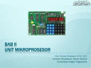
Model of microprocessor kit 2/23/2025 9
MICROPROCESSOR AND ITS OPERATIONS All the various functions performed by the microprocessor can be classified in three general categories. Microprocessor initiated operations Internal operations Peripheral or externally initiated operations To perform these functions, the microprocessor requires a group of logic circuits and a set of signals called control signals. The term microprocessor unit (MPU) is defined as a group of device that can perform these functions with necessary set of signals. It is similar to CPU (Central processing unit) of a computer. 2/23/2025 10
i) Microprocessor initiated operations and 8085 bus organization The microprocessor unit (MPU) performs mainly four operations; Memory read: Reads data (or instructions) from memory Memory write: Writes data (or instructions) into memory I/O read: Accepts data from input devices I/O write: Sends data to output devices All these operations are part of the communications process between the MPU and peripheral devices. To communicate with a peripheral (or a memory location), the MPU needs to perform the following steps Step 1: Step 2: Step 3: Identify the peripheral or the memory location Transfer binary information (data and instruction) Provide timing or synchronization signals. 2/23/2025 11
Bus Structure The 8085 MPU performs these functions using buses. A bus groups is group of conducting lines that carries address, data and control signals. There are Address bus Data bus Control bus The bus structure is shown in fig.3 Address bus The group of conducting lines that carries address are called address bus. The address bus is a group of 16 lines generally identified as A0 to A15. It is unidirectional- bits flow only in one direction i.e., from the MPU to peripheral devices. It performs the first function; identifying peripheral device or memory devices (step 1). Each peripheral or memory devices is identified by a binary number called address. Address bus is used to carry 16-bit address/lines. 2/23/2025 12
2/23/2025 13
Data bus The group of conducting lines that carries data are called data bus. The data bus is a group of 8 lines. It is a bidirectional. i.e., data flow in both directions between the MPU and memory and peripheral devices. It performs the second function; transferring binary information (step 2). The eight data lines enable the MPU to manipulate 8-bit data ranging from 00H to FFH (28 = 256 numbers) The largest number that can appear on the data bus is 1111 1111 (25510). The 8085 is known as 8-bit microprocessor. The 8086 has 16 data lines and it is known as 16-bit microprocessor. 2/23/2025 14
Control bus The group of conducting lines that carries control signals are called control bus. It is unidirectional. The control bus is comprised of various single lines that carry synchronization signals. It performs the third function; providing timing signals (step 3). It is not group of lines but individual lines that provide a pulse to indicate an MPU operation. The four control signals are memory read, memory write, I/O read and I/O write. 2/23/2025 15
ii) Internal operations The microprocessor determines how and what operations can be performed with the data. These operations are; Store 8-it data Perform arithmetic and logical operations Test for condition Sequence the execution of instructions Store data temporarily during execution in the defined R/W memory locations called stack To perform these operations, the microprocessor requires registers, an arithmetic/logic unit (ALU), control logic and internal buses. Fig.4 shows the programming model of 8085 displaying the internal registers and the accumulator. 2/23/2025 16
8085 Programmable registers 2/23/2025 17
iii) Peripheral or externally initiated operations External devices (or signals) can initiate the following operations Reset Interrupt Ready Hold 2/23/2025 18
8085 IC 2/23/2025 19
8085 MICROPROCESSOR PINOUT AND SIGNALS The 8085A (commonly known as the 8085) is an 8-bit general purpose microprocessor capable of 64K (216 rounded off to 64,000 = 64K) of memory. =65536 The device has 40 pins. Fig.5 shows the pinout of 8085 microprocessor. 2/23/2025 20
i) Address bus The 8085 has 16 signal lines (pins) that are used as the address bus. These lines are split into two segments; A15-A8 and AD7-AD0. The eight signals lines A15-A8 are unidirectional and used for the most significant bits (MSB), called the high-order address. 2/23/2025 21
ii) Multiplexed Address/Data bus The signal lines AD7-AD0 are bidirectional. They are used the low-order address bus as well as the data bus. In executing an instruction, during the earlier part of the cycle, these lines are used as the low-order address bus. During the later part of the cycle, these lines are used as the data bus. Hence it is known as multiplexing the bus. 2/23/2025 22
iii) Control and Status signals This group of signals includes two control signals (?? and ??), three status signals (IO/ ?, S0 and S1) and one special signal ALE. ALE: (Address Latch Enable) This is positive going pulse generated every time the 8085 begins an operation (machine cycle). It indicates that the bits on AD7-AD0 are address bits. This signal is used primarily to latch the low-order address from the multiplexed bus and generate a separate set of eight address lines A7-A0. ??-Read: This is a Read control signal (active low). This signal indicates that the selected I/O or memory device is to be read and data are available on the data bus. ?? A over bar on the signal, indicates that it is active low. (i.e., the signal is normally high and when the signal is activated it is low). 2/23/2025 23
??-Write: This is a Write control signal (active low). This signal indicates that the data on the data bus are to be written into a selected memory or I/O location. IO/ ?: This is a status signal used to differentiate between I/O and memory operation. When it is high, it indicates an I/O operation; when it is low, it indicates a memory operation. S1 and S0: This status signals sent by microprocessor and can be used to know the type of current operation the 8085 performs. This is given in Table. 2/23/2025 24
S1 0 0 1 1 S0 Status 0 1 0 1 Halt write read Opcode fetch 2/23/2025 25
iv) Power supply and frequency signals: Vcc : +5 V power supply Vss :Ground reference X1, X2: A crystal is connected at these two pins. The frequency is internally divided by two; to operate a system at 3 MHz, the crystal should have a frequency of 6 MHz. CLK (OUT)- Clock Output: This signal can be used as the system clock for other devices. 2/23/2025 26
v) Externally initiated signals: The 8085 has five interrupt signals that can be used to interrupt a program execution. INTR (Input): Interrupt Request- this used as a general purpose interrupt. ???? (Output): Interrupt Acknowledge-this is used to acknowledge an interrupt. RST 7.5(Inputs): Restart Interrupts: These are vectored interrupts that transfer the program control to specific memory locations. They have higher priorities than the INTR interrupt. Among these three, the priority order is 7.5,6.5 and 5.5. TRAP (Input): This is a nonmaskable interrupt and has the highest priority. 2/23/2025 27
In addition to the interrupts, three pins-RESET, HOLD and READY-accept the externally initiated signals as inputs. HOLD (Input): This signal indicates that a peripheral such as a DMA (Direct Memory Access) controller is requesting the used of the address and data buses. HLDA (Output): Hold Acknowledge- this signal acknowledges the HOLD request. READY (Input): This signal is used to delay the microprocessor Read or Write cycles until a slow responding pehripheral is ready to send or accept data. When this signal goes low, the microprocessor waits for an integral number of clock cycles until it gives high. ????? ??: When the signal on this pin goes low, the program counter is set to zero, the buses are tri-stated and the MPU is reset. RESET OUT: This signal indicates that the MPU is being reset. The signal can be used to reset other devices 2/23/2025 28
vi) Serial I/O Ports: The 8085 has two signals to implement the serial transmission; SID (serial input data) and SOD (serial output data). In serial transmission, data bits are sent over a single line, one bit at a time, such as the transmission over telephone lines. 2/23/2025 29
Reference Books 2/23/2025 30


")


 Microprocessor initiated operations and 8085 bus")


 Internal operations")

 Peripheral or externally initiated operations")


 Address bus")
 Multiplexed Address/Data bus")
 Control and Status signals")


 Power supply and frequency signals:")
 Externally initiated signals:")

 Serial I/O Ports:")