Inverted-L and Inverted-F Antennas in Antenna Design
Explore the structures, current, radiation patterns, and benefits of Inverted-L and Inverted-F antennas for different applications, along with insights on radiation resistance and impedance matching. Learn about the advantages and considerations of these antenna types in antenna design.

Download Presentation

Please find below an Image/Link to download the presentation.
The content on the website is provided AS IS for your information and personal use only. It may not be sold, licensed, or shared on other websites without obtaining consent from the author. If you encounter any issues during the download, it is possible that the publisher has removed the file from their server.
You are allowed to download the files provided on this website for personal or commercial use, subject to the condition that they are used lawfully. All files are the property of their respective owners.
The content on the website is provided AS IS for your information and personal use only. It may not be sold, licensed, or shared on other websites without obtaining consent from the author.
E N D
Presentation Transcript
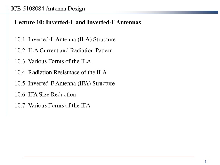
ICE-5108084 Antenna Design Lecture 10: Inverted-L and Inverted-F Antennas 10.1 Inverted-L Antenna (ILA) Structure 10.2 ILA Current and Radiation Pattern 10.3 Various Forms of the ILA 10.4 Radiation Resistnace of the ILA 10.5 Inverted-F Antenna (IFA) Structure 10.6 IFA Size Reduction 10.7 Various Forms of the IFA 1
10.1 Inverted-L Antenna (ILA) Structure Why ILA? - To make a monopole antenna low profile: 10-25% of the monopole height - Low profile = Low height - f = 10 MHz, = 30 m, Hmonopole= 7 m, HILA= 2.1 m Pros of ILA: low profile Cons of ILA: imedance matching required + narrower bandwidth 2
10.2 ILA Current and Radiation Pattern Current on ILA and Radiation Pattern of ILA on the real Earth f f1, L 1/2 f = 2 f1, L = 1 f = 3 f1, L = 1.5 1 3
Radiation Pattern of ILA - Vector sum of fields by vertical current and horizontal current 4
10.3 Various Forms of the ILA - ILA for HF Communication on the ground - ILA for mobile NVIS communication 5
- ILA for missile telemetry - ILA variants 6
10.4 Radiation Resistance of the ILA Radiation resistance RVdue to vertial current: - Uniform current approximation: ideal dipole 2 L 2 V = 80 R rv - Monopole impedance: half the dipole impedance 2 L 1 2 2 V = = 40 R R V r Radiation resistance RHdue to horizontal current: - Short ideal dipole above the ground plane 2 2 3 L 32 L V H = (120 ) R rh 15 - Sinusoidal current dipole above the ground plane: multiply it with (2/ )^2 2 2 2 L 2 L 2 V H = = 1024 R R H rh Radiation resistance of an ILA: - Geometric sum Example: LV= 0.07 , LH= 0.15 RV= 1.9 , RH= 1.1 , RILA= 5.9 RILA= 6.6 (by CST Studio) + + 2 ILA R R R R R V H V H 7
10.5 Inverted-F Antenna (IFA) Structure Why IFA? - ILA impeance: 7 j 22 -Add an impedance-match loop structure to ILA IFA -Adjust S to make the IFA impedance be 50 . Pros of IFA: low profile + small size Cons of IFA: narrower bandwidth 8
10.6 IFA Size Reduction Meander line IFA - Reduce LHby meandering 9
10.7 Various Forms of the IFA USB dongle Bluetooth, WiFi: 2-element MIMO WiFi: Miniature dielectric chip antenna: 10
Wideband PIFA (planar inverted-F antenna) Mobile phone intenna (internal antenna) - LDS (laser direct structuring) technology for 3D antenna 11
ICE-5108084 Antenna Design Lecture 10: Inverted-L and Inverted-F Antennas 12

 Structure")


 Structure")


")