JFET Amplifiers

JFET amplifiers use junction field-effect transistors, offering high input impedance characteristics. Learn about the working of JFET as an amplifier and how it amplifies weak input signals through the alteration of gate-to-source voltage, resulting in signal amplification through drain current. Explore the impact of reverse voltage changes on the depletion region width and drain current, illustrating the amplification process in JFET circuits.

Download Presentation

Please find below an Image/Link to download the presentation.
The content on the website is provided AS IS for your information and personal use only. It may not be sold, licensed, or shared on other websites without obtaining consent from the author.If you encounter any issues during the download, it is possible that the publisher has removed the file from their server.
You are allowed to download the files provided on this website for personal or commercial use, subject to the condition that they are used lawfully. All files are the property of their respective owners.
The content on the website is provided AS IS for your information and personal use only. It may not be sold, licensed, or shared on other websites without obtaining consent from the author.
E N D
Presentation Transcript
JFET AS AN AMPLIFIER
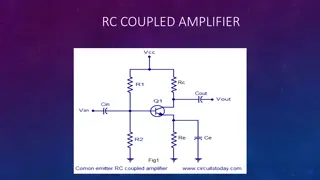
JFET AMPLIFIER JFET amplifier circuit common Source JFET Amplifier uses junction field effect transistors as its main active device offering high input impedance characteristics. Transistor amplifier circuits such as the common emitter amplifier are made using Bipolar Transistors, but small signal amplifiers can also be made using Field Effect Transistors
Working of JFET The working procedure of JFET as an amplifier can be easily conceived even if we know a little about vacuum tube. In case of a vacuum tube, we supply the weak input signal between its grid and cathode. This creates a large change in the output obtained at plate circuit. This large change is a desired feature here. This is something which creates an amplifier.
Working of JFET The input signal which is weak in magnitude is applied by AC signal source. It is supplied as alternate positive, negative half cycles of AC. When the AC signal is applied to the input circuitry, it will start altering the gate to source voltage.
working f the reverse voltage falls down, then the width of the depletion region inside the channel will starts decreasing. We have already discussed in our previous article that if the width of the depletion region starts decreasing, then the channel width will be increased. Consequently, the magnitude of charge carriers (Electrons in case of N-channel JFET) flowing from source to drain will increase.
This will directly contribute to increase in the drain current. The load resistor is connected to the output circuit. The current flowing through it will create a voltage drop, and thus large current will flow through it. This leads to amplification of the signal. And thus JFET as an amplifier is designed.
Increase in reverse voltage at gate-source terminal If the AC signal applied at the input terminal will increase the reverse voltage, then the width of the depletion region will start increasing. Due to this, the drain current will starts decreasing. And again the small change in input will cause a large change across the load resistor. This performs the amplification action in JFET
PERFORMANCE PARAMETERS OF JFET AC DRAIN RESISTANCE 1.AC Drain Resistance: The ratio of change in voltage across the drain-source terminal and the change in drain current is termed as AC drain resistance. But the ratio should be considered at a point when the gate-source voltage is kept constant. Its value is in range of 10 k to 1 M . It is also referred as dynamic resistance (rd), it should not be confused with the resistance of channel (RDS), Rdsis purely DC while rdis not.
DC DRAIN RESISTANCE 2.DC Drain Resistance: RDSis a symbol used for DC drain resistance. It is the ratio between the change in drain-source voltage and the change in drain current. The value of DC drain resistance is static. Thus it is also termed as static or ohmic resistance.
TRANSCONDUCTANCE 3.Transconductance: It is the ratio between the change in drain current and the change in gate-source voltage but at constant drain-source voltage. It is represented by gm.
AMPLIFICATION FACTOR 4.Amplification factor: The amplification factor is obtained by determining the ratio between the change in drain-source voltage with respect to change in gate-source voltage but keeping the value of drain current constant.
AC DRAIN RESISTANCE X TRANSCONDUCTANCE It is represented by . The value of amplification factor can be high as 100
SIGNIFICANCE OF AMPLIFICATION The Significance of the amplification factor is that it helps to determine the control of gate to source voltage on the value of drain current in comparison to that of the drain to source voltage.
JFET AMPLIFIER Using JFET as an amplifier To understand, how a JFET works as an amplifier, first we should be well aware of the fact that how does an amplifier work. It takes an input signal which is weak in magnitude and amplifies it by its internal circuit. The weak signal applied at its input circuit causes a large change in its output circuit.
Since the N-Channel JFET is a depletion mode device and is normally ON, a negative gate voltage with respect to the source is required to modulate or control the drain current. This negative voltage can be provided by biasing from a separate power supply voltage or by a self biasing arrangement as long as a steady current flows through the JFET even when there is no input signal present and Vg maintains a reverse bias of the gate-source pn junction.
As with the common emitter bipolar circuit, the DC load line for the common source JFET amplifier produces a straight line equation whose gradient is given as: -1/(Rd + Rs) and that it crosses the vertical Id axis at point A equal to Vdd/(Rd + Rs). The other end of the load line crosses the horizontal axis at point B which is equal to the supply voltage, Vdd.
The actual position of the Q-point on the DC load line is generally positioned at the mid center point of the load line (for class-A operation) and is determined by the mean value of Vg which is biased negatively as the JFET is a depletion-mode device. Like the bipolar common emitter amplifier the output of the Common Source JFET Amplifier is 180oout of phase with the input signal.
One of the main disadvantages of using Depletion-mode JFET is that they need to be negatively biased. Should this bias fail for any reason the gate-source voltage may rise and become positive causing an increase in drain current resulting in failure of the drain voltage, Vd.
APPLICATION OF JFET JFET Amplifier Current and Power Gains We said previously that the input current, Ig of a common source JFET amplifier is very small because of the extremely high gate impedance, Rg. A common source JFET amplifier therefore has a very good ratio between its input and output impedances and for any amount of output current, IOUTthe JFET amplifier will have very high current gain Ai.