John Deere 300 Series OEM Engine Service Repair Manual Instant Download 1
John Deere 300 Series OEM Engine Service Repair Manual Instant Download 1

Download Presentation

Please find below an Image/Link to download the presentation.
The content on the website is provided AS IS for your information and personal use only. It may not be sold, licensed, or shared on other websites without obtaining consent from the author. If you encounter any issues during the download, it is possible that the publisher has removed the file from their server.
You are allowed to download the files provided on this website for personal or commercial use, subject to the condition that they are used lawfully. All files are the property of their respective owners.
The content on the website is provided AS IS for your information and personal use only. It may not be sold, licensed, or shared on other websites without obtaining consent from the author.
E N D
Presentation Transcript
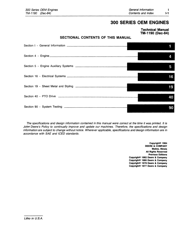
1 General Information Contents and Index 300 Series OEM Engines TM-1190 (Dec-84) 1-1 300 SERIES OEM ENGINES Technical Manual TM-1190 (Dec-S4) SECTIONAL CONTENTS OF THIS MANUAL Section I - General Information ________________ _ Section 4 - Engine _______________________ _ Section 5 - Engine Auxiliary Systems Section 16 - Electrical Systems __________________ _ Section 19 - Sheet Metal and Styling Section 40 - PTO Drive Section 90 - System Testing The specifications and design information contained in this manual were correct at the time it was printed. It is JohtrDeere's Policy to continually improve and update our machines. Therefore, the specifications and design information are subject to change without notice. Wherever applicable, specifications and design information are in accordance with SAE and ICED standards. CopyrighNl 1984 DEERE Ie COMPANY Moline, Illinois All Rights Reserved Previous Editions CopyrighNl1982 Deere Ie Company CopyrighNl 1980 Deere Ie Company CopyrighNl1978 Deere Ie Company Copyrightc> 1977 Deere Ie Company Litho in U.S.A.
1 1-2 General Information Contents and Index 300 Series OEM Engines TM-1190 (Aug-78) INTRODUCTION II r t. l' " Use FOS Manuals for Reference Use Technical Manuals for Actual Service This technical manual is part of a twin concept of service: This technical manual was planned and written for you-an experienced service technician. Keep it in a permanent binder in the shop where it is handy. Refer to it whenever in doubt about correct service proce- dures or specifications. The two kinds of manuals work as a team to give you both the general background and technical details of shop service. Some features of this manual: .FOS Manuals-for reference Inside front cover - "Table of Contents". Fundamentals of Service (FOS) Manuals cover basic theory of operation, fundamentals of trouble shooting, general maintenance, and basic types of failures and their causes. FOS Manuals are for training new personnel and for reference by experienced ser- vice technicians. E] symbol like the one at the left is used in the D TM to identify the reference . Section I - Contents Sections 4 through 40 - Removal, repair, testing (components removed), installation, and adjustment. Section 90 - Detailed explanation of system operation, diagnosis, visual inspection, testing, and adjustments. When a service technician should refer to a FOS Manual for more information, a FOS FeS Specifications grouped and illustrated at the end of each section. Technical Manuals-for actual service Technical Manuals are concise service guides for a specific machine. Technical manuals are on-the-job guides containing only the vital information needed by an experienced service technician. Litho in U.S.A.
300 Series OEM Engines TM-1190 (Dec-82) General Information Contents and Index 1 1-3 SECTION ANO GROUP CONTENTS OF THIS MANUAL SECTION I - GENERAL INFORMATION Group I - Contents SECTION 5 - ENGINE AUXILIARY SYSTEMS Group 0510 - Cooling Systems Group 0515 - Speed Controls Group 0520 - Intake Systems Group 0599 - Specifications and Special Tools SECTION 4 - ENGINE Group 0400 - Removal and Installation Group 0401 - Crankshaft and Main Bearings Group 0402 - Camshaft and Valve Actuating Means Group 0403 - Connecting Rods and Pistons Group 0404 - Cylinder Block Group 0407 - Oiling System Group 0408 - Ventilating System Group 0409 - Cylinder Head and Valves Group 0410 - Exhaust Manifold Group 0413 - Fuel Injection System Group 0414 - Intake Manifold Group 0415 - Engine Balancer Group 0416 - Turbocharger Group 0417 - Water Pump Group 0418 - Thermostats, Housing and Piping Group 0419 - Engine Oil Cooler Group 0420 - Fuel Filter Group 0421 - Fuel Transfer Pump Group 0422 - Starting Motor and Fastening Group 0423 - Alternator and Generator Mountings Group 0429 - Fan Drive Group 0433 - Flywheel, Housing and Fastenings Group 0499 - Specifications and Special Tools I SECTION 16 - ELECTRICAL SYSTEMS Group 1672 - Alternator, Regulator and Charging System Wiring Group 1674 - Wiring Harness and Switches Group 1676 - Instruments and Indicators Group 1699 - Specifications and Special Tools SECTION 19 - SHEET METAL AND STYLING Group 1910 - Hood or Engine Enclosure SECTION 40 - PTO DRIVE Group 4052 - PTO Clutch Group 4099 - Specifications and Special Tools SECTION 90 - SYSTEM TESTING Group 9010 - Engine Group 9015 - Electrical System Group 9035 - Specifications and Special Tools OEM ENGINES SERVICEO BY THIS TECHNICAL MANUAL 3-1640 3-1790 4-2190 4-2390 4-239T 4-2760 4-276T 6-3290 6-3590 6-359T 6-4140 6-414T Litho in U.S.A.
https://www.ebooklibonline.com Hello dear friend! Thank you very much for reading. Enter the link into your browser. The full manual is available for immediate download. https://www.ebooklibonline.com
300 Series OEM Engines TM-1190 (Nov-78) 1 1 4 General Information Contents and Index Accessible Hardware Torque Values The types of bolts and cap screws are identified by head markings as follows: The table below gives correct torque values for various bolts and cap screws. The table lists torques in the U.S. unit of measure (lb-ft), SI metrics (Nm) and conventional metrics (kg/m). Most hardware used is high-strength (note dashes on hex. heads). Plain Head: regular machine bolts and cap screws. 3-Dash Head: tempered steel high-strength bolts and cap screws . 6-Dash Head: tempered steel extra high-strength bolts and cap screws. Machine bolts and cap screws 7/8-inch (22.2 mm) and larger are sometimes formed hot rather than cold, which accounts for the lower torque. RECOMMENDED TORQUE - COARSE AND FINE THREADS F 0 0 @ /\ G ED t\ /, B 0 PLAIN HEAD BOLT DIAMETER SIX DASHES THREE DASHES Nm 19 41 68 108 163 237 325 576 929 1396 1979 2793 Nm 14 27 47 75 115 176 230 407 603 908 1234 1695 Kg-m LB-FT 14 30 50 80 120 175 240 425 685 1030 1460 2060 Kg-m LB-FT NOT USED NOT USED NOT USED 35 55 75 105 185 160 250 330 480 Nm LB-FT 10 20 35 55 85 130 170 300 445 670 910 1250 Kg-m NOT USED NOT USED NOT USED 5 8 10 15 26 22 35 46 66 NOT USED NOT USED NOT USED 47 75 102 142 251 217 339 447 651 1/4 5/16 3/8 7/16 1/2 9/16 5/8 3/4 7/8 1 1-1/8 1-1/4 143720 2 4 7 11 17 24 33 59 95 142 202 285 1 3 5 8 12 18 24 42 62 93 126 173 Litho in U.S.A.
300 Series OEM Engines TM-1190 (Dec-82) General Information Contents and Index 1 1-5 ALPHABETICAL INDEX A Engine: -Continued Fuel filter ........................... 0420-1 Fuel injection system .................. 0413-1 Fuel transfer pump ................... 0421-1 Air cleaner ............................ 0520-1 Alternator and generator mounting ......... 0423-1 Alternator, regulator and charging system wiring ........................ 1672-3 Amp meter ............................ 1676-2 Intake manifold ...................... 0414-1 I Oil cooler ........................... 0419-1 Oiling system ........................ 0407-1 Removal and installation ............... 0400-5 Starting motor and fastenings ........... 0422-1 Thermostats, housings and water piping ............................ 0418-1 Turbocharger ........................ 0416-1 Ventilating system .................... 0408-1 Water pump ......................... 0417-1 Engine auxiliary systems: Cooling system ...................... 0510-3 Intake system ....................... 0520-1 Speed controls ....................... 0515-1 Engine removal and installation ............ 0400-5 Engine system testing and adjustments: Compression pressure test ............. 9010-9 Engine cooling system test ............ 9010-11 Engine oil pressure test. .............. 9010-10 Engine preformance test using turbocharger boost pressure ......... 9010-14 Fuel transfer pump pressure test ....... 9010-11 Governor speed droop adjustment ...... 9010-11 Injection pump cam advance ........... 9010-13 Speed control linkage adjustment ....... 9010-12 Exhaust manifold ....................... 0410-1 B Balancer shafts ........................ 0415-1 C Camshaft and valve actuating means ....... 0402-1 Charging circuit testing (Delco-Remy alternator) ........................... 9015-8 Charging circuit testing (Motorola alternator) . 9015-5 Connecting rods and pistons .............. 0403-1 Cooling manifold ....................... 0418-1 Cooling system, engine .................. 0510-3 Crankshaft and main bearings ............. 0401-1 Crankshaft front oil seal ................. 0402-3 Crankshaft front wear ring ............... 0401-6 Crankshaft gear ........................ 0401-5 Crankshaft rear oil seal .................. 0401-6 Crankshaft rear wear ring ................ 0401-6 Crankshaft pulley ....................... 0429-2 Cylinder block ......................... 0404-1 Cylinder head and valves ................ 0409-1 D Delco-Remy alternator ................... 1672-3 Delco-Remy starting motor ............... 0422-1 Diagnosing malfunctions: Engine system testing ................. 9010-5 Dipstick ............................. 0407-18 F Fan belt .............................. 0429-1 Fan drive ............................. 0429-1 Filter, fuel . . . . . . . . . . . . . . . . . . . . . . . . . . . . . 0420-1 Flywheel, housing and fastenings .......... 0433-2 Fuel filter ............................. 0420-1 Fuel injection nozzles .................. 0413-20 Fuel injection pump ..................... 0413-1 Fuel transfer pump ..................... 0421-1 E Electrical schematic .................... 9015-11 Electrical system ....................... 1672-1 Electrical system testing ................. 9015-1 Charging circuit ...................... 9015-5 Starting circuit ....................... 9015-1 Engine: Alternator and generator mounting ....... 0423-1 Camshaft and valve actuating means ..... 0402-1 Connecting rods and pistons ............ 0403-1 Crankshaft and main bearings ........... 0401-1 Cylinder block ....................... 0404-1 Cylinder head and valves .............. 0409-1 Engine balancer ...................... 0415-1 Exhaust manifold ..................... 0410-1 Fan drive . . . . . . . . . . . . . . . . . . . . . . . . . . . 0429-1 Flywheel, housing and fastenings ........ 0433-1 G Gauge, pressure ....................... 1676-3 Gauge, temperature ..................... 1676-3 H Hood ................................ 1910-3 Hour meter ........................... 1676-2 Litho in U.S.A.
General Information Contents and Index I 1-6 300 Series OEM Engines TM-1190 (Dec-82) S Instruments and indicators ............... 1676-1 Amp meter .......................... 1676-2 Hour meter ......................... 1676-2 Pressure gauge ...................... 1676-3 Safety switch ........................ 1676-4 Tachometer ......................... 1676-1 Temperature gauge ................... 1676-3 Intake manifold ........................ 0414-1 Intake system ......................... 0520-1 Safety switch .......................... 1676-4 Special tools: Camshaft and valve actuating means .... 0499-94 Connecting rods and pistons ........... 0499-96 Crankshaft and main bearings .......... 0499-93 Cylinder block ...................... 0499-97 Cylinder head and valves ............. 0499-99 Electrical system ..................... 1699-4 Electrical system testing ............... 9035-8 Engine balancer .................... 0499-103 Engine removal and installation ......... 0499-92 Engine system testing ................. 9035-4 Fuel injection system ................ 0499-101 Oiling system, engine ................ 0499-98 Starting motor and fastenings ......... 0499-106 Turbocharger ...................... 0499-104 Water pump ....................... 0499-105 Specifications and torque values: Camshaft and valve actuating means ..... 0499-4 Connecting rods and pistons ........... 0499-~ 1 Crankshaft and main bearings ........... 0499-2 Cylinder block ...................... 0499-15 Cylinder head and valves ............. 0499-23 Electrical system ..................... 1699-1 Electrical system testing ............... 9035-6 Engine balancer ..................... 0499-79 Engine break-in ...................... 0499-1 Engine cooling system ................. 0599-1 Engine system testing ................. 9035-1 Fan drive .......................... 0499-90 Flywheel, housing and fastenings ....... 0499-90 Fuel injection system ................. 0499-27 Intake manifold ..................... 0499-78 Oil cooler, engine .................... 0499-84 Oiling system, engine ................ 0499-17 PTO clutch .......................... 4099-1 Starting motor and fastenings .......... 0499-85 Thermostats, housings and water piping ........................... 0499-83 Turbocharger ....................... 0499-80 Water pump ........................ 0499-81 Speed controls, engine .................. 0515-1 Starting circuit testing ................... 9015-1 Starting motor, Oelco-Remy .............. 0422-1 Starting motor, John Deere .............. 0422-11 Switch, safety ......................... 1676-4 II J John Deere starting motor ............... 0422-11 M Malfunctions, diagnosing: Engine system testing ................. 9010-5 Manifold, exhaust ...................... 0410-1 Manifold, intake ........................ 0414-1 Motorola alternator ..................... 1672-9 N Nozzle, fuel injection ................... 0413-11 o Oil bypass valve ....................... 0407-4 Oil cooler, engine ....................... 0419-1 3-1640,4-2190,4-2390, 4-239T, 6-3290, 6-3590 and 6-359T engines .......... 0419-1 4-2760, 4-276T, 6-4140 and '6-414T engines .................... 0419-3 Oil filter .............................. 0407-1 Oil filter nipple ......................... 0407-2 Oiling system, engine ................... 0407-1 Oil pan ............................... 0407-4 Oil pressure control valve ................ 0407-5 Oil pump ............................ 0407-10 '- p Pressure gauge ........................ 1676-3 PTO clutch ............................ 4052-3 Pump, engine oil ....................... 0407-1 Pump, engine water ..................... 0417-1 Pump, fuel injection ..................... 0413-1 Pump, fuel transfer ..................... 0421-1 R Radiator .............................. 0510-3 Rocker arms and push rods ............. 0402-17 Rods and pistons ...................... 0403-1
J 300 Series OEM Engines TM-1190 (Dec-82) General Information Coiiients and Imfex 1-7 T V Tachometer ........................... 1676-1 Temperature gauge ..................... 1676-3 Tests and adjustments: Alternator components ............... 1672-14 Electrical system ..................... 9015-1 Engine system ....................... 9010-9 Starting motor, Delco-Remy ............ 0422-1 Starting motor, John Deere ............ 0422-12 Turbocharger ........................ 0416-2 Thermostats, housings and water piping .............................. 0418-1 Timing gear ........................... 0402-9 Timing gear cone ....................... 0402-2 Turbocharger . . . . . . . . . . . . . . . . . . . . . . . . . . 0416-1 Ventilating system ...................... 0408-1 Vertical tachometer drive ................. 0433-1 Vibration damper ....................... 0401-8 W Water pump ........................... 0417-1 Wiring harness and switches .............. 1674-1 Wiring diagram ........................ 9015-12. Litho in U.S.A.
General Information Contents and Index I 1-8 300 Series OEM Engines TM-1190 (Mar-BO) I Litho in U.S.A.
4 300 Series OEM Engines TM-1190 (Dec-82) Engine 0400-1 Removal and Instal/ation Section 4 ENGINE CONTENTS OF THIS SECTION Page Page I GROUP 0400 - REMOVAL AND GROUP 0402 - CAMSHAFT AND VALVE ACTUATING MEANS-Continued Timing Gear ......................... 0402-9 Removal .......................... 0402-9 Repair .......................... 0402-11 Installation ....................... 0402-12 Rocker Arms and Push Rods .......... 0402-17 Removal ......................... 0402-17 Repair .......................... 0402-17 Installation ....................... 0402-18 Valve Clearance Adjustment ........... 0402-19 INSTALLATION General Information ................... 0400-5 Removal ............................ 0400-7 Installation ......................... 0400-10 GROUP 0401 - CRANKSHAFT AND MAIN BEARINGS Crankshaft and Main Bearings .......... 0401-1 Removal .......................... 0401-1 Crankshaft End Play ................ 0401-1 Repair ........................... 0401-2 Installation ........................ 0401-3 Crankshaft gear ...................... 0401-5 Removal .......................... 0401-5 Repair ........................... 0401-5 Crankshaft Front Wear Ring ............ 0401-6 Removal .......................... 0401-6 Installation .... : ................... 0401-6 Crankshaft Front Oil Seal .............. 0401-6 Crankshaft Rear Oil Seal and Wear Ring .. 0401-6 Removal .......................... 0401-6 Repair ........................... 0401-6 Installation ........................ 0401-7 Vibration Damper ..................... 0401-8 Installation ........................ 0401-8 GROUP 0403 - CONNECTING RODS AND PISTONS Removal ............................ 0403-1 Repair ............................. 0403-3 Installation .......................... 0403-9 GROUP 0404 - CYLINDER BLOCK Removal ............................ 0404-1 Repair ............................. 0404-3 Installation .......................... 0404-6 GROUP 0407 - OILING SYSTEM Oil Filter ............................ 0407-1 Removal ....................... ' ... 0407-1 Installation ........................ 0407-1 Oil Filter Nipple ...................... 0407-1 Removal .......................... 0407-2 Installation ........................ 0407-3 Oil Pan Removal .......................... 0407-4 Repair ........................... 0407-4 Installation ........................ 0407-4 Oil Bypass Valve Removal .......................... 0407-4 Repair ........................... 0407-4 Installation ........................ 0407-4 Oil Pressure Control Valve 3-1640,3-1790, 4-219D, 4-239D, 4-239T, 6-3290,6-3590, or 6-359T Engine ..... 0407-5 Removal ........................ 0407-5 Repair ......................... 0407-5 Installation ...................... 0407-6 GROUP 0402 - CAMSHAFT AND VALVE ACTUATING MEANS Valve Lift Check ..................... 0402-1 Timing Gear Cover ................... 0402-2 Removal .......................... 0402-2 Repair ........................... 0402-2 Installation ........................ 0402-3 Crankshaft Front Oil Seal .............. 0402-3 Removal .......................... 0402-3 Installation ........................ 0402-3 Camshaft ........................... 0402-3 Removal .......................... 0402-3 Repair ........................... 0402-6 Installation ........................ 0402-7 Contents continued on next page Litho in U.S.A.
Engine Removal and Installation 4 0400-2 300 Series OEM Engines TM-1190 (Dec-82) CONTENTS OF THIS SECTION-Continued Page Page GROUP 0407 - OILING SYSTEM-Continued Oil Pressure Control Valve-Continued 4-2760, 4-276T, 6-4140 or 6-414T Engine ................... 0407-7 Removal ........................ 0407-7 Disassembly ..................... 0407-7 Repair ......................... 0407-8 Assembly .. ' ..................... 0407-8 Installation ...................... 0407-9 Oil Pump 3-1640,3-1790,4-2190, 6-3290, or 6-3590 Engine .......... 0407-10 Removal ....................... 0407-10 Inspection and Disassembly ....... 0407-10 Repair ........................ 0407-12 Assembly ...................... 0407-12 Installation .. . . . . . . . . . . . . . . . . . . . 0407-13 4-239T, 4-2760, 4-276T, 6-359T, 6-4140, or 6-414T Engine ........... 0407-14 Removal ....................... 0407-14 Inspection and Disassembly ....... 0407-14 Repair ........................ 0407-16 Assembly ...................... 0407-16 Installation ..................... 0407-17 Dipstick and Dipstick Nipple ........... 0407-18 Removal ......................... 0407-18 Repair .......................... 0407-18 Installation ....................... 0407-19 GROUP 0413 - FUEL INJECTION SYSTEM Fuel Injection Pump ................... 0413-1 Removal .......................... 0413-1 Repair ........................... 0413-6 Installation ........................ 0413-9 Bleeding ......................... 0413-19 Fuel Injection Nozzles ................ 0413-20 Removal ......................... 0413-20 Repair .......................... 0413-21 Installation ....................... 0413-22 GROUP 0414 - INTAKE MANIFOLD Removal ............................ 0414-1 Repair ............................. 0414-1 Installation .......................... 0414-1 GROUP 0415 - ENGINE BALANCER General Information ................... 0415-1 Removal. ........................... 0415-1 Repair ............................. 0415-2 Installation .......................... 0415-3 GROUP 0416 - TURBOCHARGER General Information ................... 0416-1 Removal. ........................... 0416-1 Testing ............................. 0416-2 Radial Bearing Movement ............ 0416-2 Axial Bearing Movement ............. 0416-2 Repair .:-. -;-. . . . . . . . . . . . . . . . . . . . . . . . . 0416-2 Installation . . . . . . . . . . . . . . . . . . . . . . . . . . 0416-8 GROUP 0408 - VENTILATING SYSTEM General Information ................... 0408-1 Removal ............................ 0408-1 Repair ............................. 0408-1 Installation .......................... 0408-i GROUP 0417 - WATER PUMP Removal. ........................... 0417-1 Disassembly 3-164,3-1790,4-2190,4-2390, 4-2760, or 6-3290 Engine ........... 0417-2 4-239T, 4-276T, 6-3590, 6-359T, 6-4140, or 6-414T Engine ..... 0417-3 Repair ............................. 0417-4 Assembly ........................... 0417-5 Installation .......................... 0417-7 GROUP 0409 - CYLINDER HEAD AND VALVES Removal ............................ 0409-1 Disassembly ......................... 0409-2 Repair ............................. 0409-2 Assembly ........................... 0409-7 Installation .......................... 0409-7 GROUP 0410 - EXHAUST MANIFOLD General Information ................... 041 0-1 Removal ............................ 0410-1 Repair ............................. 0410-1 Installation .......................... 0410-1 GROUP 0418 - THERMOSTATS, HOUSINGS, AND WATER PIPING Thermostat ......................... 0418-1 Removal .......................... 0418-1 Repair ........................... 0418-2 Installation ........................ 0418-2 Contents continued on next page Litho in U.S.A.
300 Series OEM Engines TM-1190 (Dec-82) Engine 4 Removal and Installation 0400-3 CONTENTS OF THIS SECTION-Continued Page Page GROUP 0419 - OIL COOLER 3-1640, 3-179D, 4-2190 and 6-329D Engines: Removal .......................... 0419-1 Repair ........................... 0419-2 Installation ........................ 0419-2 4-2760, 4-276T, 6-4140 and 6-414T Engines: Removal .......................... 0419-3 Repair ........................... 0419-3 Installation ........................ 0419-5 GROUP 0429 - FAN DRIVE Fan Belt ............................ 0429-1 Removal .......................... 0429-1 Repair ........................... 0429-1 Installation ........................ 0429-1 Crankshaft Pulley ..................... 0429-2 Removal .......................... 0429-2 I Repair ........................... 0429-2 Installation ........................ 0429-3 ; GROUP 0433 - FLYWHEEL, HOUSING, AND FASTENINGS Vertical Tachometer Drive .............. 0433-1 Removal .......................... 0433-1 Repair ........................... 0433-1 Installation ........................ 0433-1 Flywheel ............................ 0433-2 Removal .......................... 0433-2 Repair ........................... 0433-2 Installation ........................ 0433-3 Flywheel Ring Gear ................... 0433-4 Removal .......................... 0433-4 Installation . . . . . . . . . . . . . . .. '. . . . . . . . 0433-4 Flywheel Housing ..................... 0433-4 Removal'. ......................... 0433-4 Repair ........................... 0433-5 Installation ........................ 0433-5 GROUP 0420 - FUEL FILTER General Information ................... 0420-1 Removal ............................ 0420-1 Installation .......................... 0420-1 GROUP 0421 - FUEL TRANSFER PUMP General Information ................... 0421-1 Removal ............................ 0421-1 Repair ............................. 0421-1 Installation .......................... 0421-2 GROUP 0422 - STARTING MOTOR AND FASTENINGS General Information ................... 0422-1 Delco-Remy Starting Motor ............. 0422-1 Removal .......................... 0422-1 Testing and Diagnosis ............... 0422-1 Testing Pull-in Windings ........... 0422-1 Testing Hold-in Windings ........... 0422-1 No Load Starting Motor Test ....... 0422-2 Repair ........................... 0422-4 Assembly ......................... 0422-8 Installation ....................... 0422-10 John Deere Starting Motor ............ 0422-11 Removal ......................... 0422-11 Tests ........................... 0422-12 Solenoid Pull-in Test ............. 0422-12 Solenoid Return Test. ............ 0422-12 No Load Test. .................. 0422-13 Repair .......................... 0422-15 Assembly ........................ 0422-20 GROUP 0499 - SPECIFICATIONS AND SPECIAL TOOLS Specifications and Torque Values: Engine Break-In .................... 0499-1 Crankshaft and Main Bearings ........ 0499-2 Camshaft and Valve Actuating Means ......................... 0499-4 Connecting Rods and Pistons ........ 0499-11 Cylinder Block .................... 0499-15 Oiling System ..................... 0499-17 Cylinder Head and Valves ........... 0499-23 GROUP 0423 - ALTERNATOR AND GENERATOR MOUNTING General Information ................... 0423-1 Removal ............................ 0423-1 Installation .......................... 0423-1 Contents continued on next page Litho in U.S.A.
4 0400-4 300 Series OEM Engines TM-1190 (Dec-84) Engine Removal and Installation CONTENTS OF THIS SECTION-Continued Page Page GROUP 0499 - SPECIFICATIONS AND SPECIAL TOOLS-Continued Specifications and Torque Values-Continued Fuel Injection System .............. 0499-27 Test Stand ....................... 0499-27 Fuel Injection Pump: R3432F900 - RE12266 ........... 0499-28 R3432F920 - RE12267 .......... 0499-28A R3448F160 - RE15699 .......... 0499-28B R3448F210 - RE15697 .......... 0499-28C R3462F950 - RE15698 .......... 0499-28D R3462F920 - RE15700 .......... 0499-28E JDB331 MD2406 - AR49904 ...... 0499-28F JDB435AL2442 - AR51747 ........ 0499-29 JDB635AL2446 - AR51568 ........ 0499-30 JDB331 CM2667 - AR66282 ....... 0499-31 DM4627MD2684 - AR66395 ....... 0499-32 JDB431 CM2701 - AR66995 ....... 0499-33 JDB635CM2757 - AR66996 ....... 0499-34 JDB435MD2793 - AR70530 ....... 0499-35 JDB435MD2802 - AR51747 ....... 0499-36 JDB435CM2819 - AR70531 ....... 0499-37 DM4627 AL2824 - AR70778 ....... 0499-38 DM4627HB2825 - AR70551 ....... 0499-39 DM4627HB2826 - AR70780 ....... 0499-40 DM4427MD2876 - AR71421 ....... 0499-41 DM4427HB2915 - AR70538 ....... 0499-42 DM4427NH2957 - AR76503 ....... 0499-43 JDB435CM2974 - AR77422 ....... 0499-44 JDB333CM3009 - AR79211 ....... 0499-45 JDB435CM3010 - AR79212 ....... 0499-46 JDB635CM3011 - AR79213 ....... 0499-47 JDB435MD3021 - AR78647 ....... 0499-48 DM4427MD3051 - AR80325 ....... 0499-49 DM4627MD3052 - AR80352 .. , ..... 0499-50 JDB435MD3053 - AR80230 ....... 0499-51 JDB635MD3142 - AR80603 ....... 0499-52 DM4627HB3220 - AR80353 ....... 0499-53 JDB435CM3223 - AR80233 ....... 0499-54 DM4427HB3224 - AR80326 ....... 0499-55 JDB635CM3243 - AR80604 ....... 0499-56 DM4427NW3262 - AR87186 ....... 0499-57 DM4627 AL3335 - AR70778 ....... 0499-58 DM4627NH3642 - AR89482 ....... 0499-59 DM4427NH3776 - AR90716 ....... 0499-60 DM4427HB3986 - AR99951 ...... 0499-60A DM4627HB3987 - AR99952 ....... 0499-61 DM4627MD4012 - AR104000 ...... 0499-62 DM4627ABE4083 - AR100427 ..... 0499-63 DM4627 ABE4118 - AR 1 00427 ..... 0499-64 DM4427AL4299 - RE16150 ...... 0499-64A DM46274444 - RE19914 .... .' ... 0499-64B Injection Pump Torque ............. 0499-65 GROUP 0499 - SPECIFICATIONS AND SPECIAL TOOLS-Continued Specifications and Torque Values-Continued Fuel Injection Nozzle: 19762 - AR56290 ............... 0499-67 20500 - AR56290 ............... 0499-68 20291 - AR68364 ............... 0499-69 20504 - AR68364 ............... 0499-70 20631 - AR73673 ............... 0499-71 22042 - AR88239 ............... 0499-72 22205 - AR88240 ............... 0499-73 22044 - AR88241 ............... 0499-74 2203 - AR89563 and AR89564 ..... 0499-75 22265 - AR90023 and AR90024 .... 0499-76 Injection Nozzle Torque ............. 0499-77 Intake Manifold ................... 0499-78 Engine Balancer ................... 0499-79 Turbocharger ..................... 0499-80 Water Pump ...................... 0499-81 Thermostats, Housings, and Water Piping ................... 0499-83 Oil Cooler ........................ 0499-84 Starting Motor and Fastenings ....... 0499-85 Fan Drive ........................ 0499-90 Flywheel, Housing, and Fastenings ..................... 0499-90 Special Tools: Removal and Installation .......... 0499-92 Crankshaft and Main Bearings ..... 0499-93 Camshaft and Valve Actuating Means ...................... 0499-94 Connecting Rods and Pistons ...... 0499-96 Cylinder Block .................. 0499-97 Oiling System ................... 0499-98 Cylinder Head and Valves ......... 0499-99 Fuel Injection System ........... 0499-101 Engine Balancer ................ 0499-103 Turbocharger .................. 0499-104 Water Pump ................... 0499-105 Starting Motor and Fastenings .... 0499-106 Litho in U.S.A.
300 Series OEM Engines TM-1190 (Dec-82) Engine 4 Removal and Installation 0400-5 Group 0400 REMOVAL AND INSTALLATION Cl GENERAL INFORMATION Learn principles of operation of engines from "Basic Engine" in Fundamentals of Service II Manual 30 - ENGINES. II Design Characteristics The 3-1640, 3-1790, 4-2190, 4-2390, 4-2760, 6- 3290, 6-3590, and 6-4140 engines have: 1. Internal combustion 2. Four strokes' per cycle 3. In-line type cylinder block 4. Oiesel fueling 5. Valves in cylinder head 6. Natural aspiration 7. Liquid coolant 8. Pressure lubrication The 4-239T, 4-276T, 6-359T, and 6-414T engines have: 1. Internal combustion 2. Four strokes per cycle 3. In-line type cylinder block 4. Oiesel fueling 5. Valves in cylinder head 6. Turbocharger 7. Liquid coolant 8. Pressure lubrication Litho in U. S.A.
Engine Engine Removal and Installation 4 0400-6 300 Series OEM Engines TM-1190 (Dec-82) Front Reference The water pump (Fig. 1) end is the "front' of the engine. I T70243 Fig. 1-Water Pump Direction of Crankshaft Rotation The crankshaft turns clockwise when viewed from the water pump end. T70244 Fig. 2-Crankshaft Rotation Firing Order 2 3 3-164 and 3-179 Engine 10001 Firing order is: 1-2-3 T70245 T70245 Fig. 3-Cylinder Arrangement Litho in U.S.A.
300 Series OEM Engines TM-1190 (Mar-80) Engine 4 0400-7 Engine Removal and Installation 4-219, 4-239, and 4-276 Engines Firing order is: 1-3-4-2 1 2 3 4 100001 I T70246 Fig. 4-Cylinder Arrangement 2 6 5 6-329, 6-359, and 6-414 Engines 3 4 /0000001 Firing order is: 1-5-3-6-2-4 T70655 Fig. 5-Cylinder Arrangement REMOVAL Disconnect battery negative (-) cable. Disconnect battery positive (+) cable from starting motor. Remove engine side shields (2, Fig. 6) (Group 1910). Remove muffler. Remove hood (1, Fig. 6) (Group 1910). A It '. CAUTION: Do not drain cooling system until upper radiator tank feels cool. , '-:;,. - - .... ~ " .' Drain engine cooling system. Fig. 6-Engine Enclosure Drain engine oil. Disconnect fuel inlet line at fuel transfer pump. Litho in U.S.A.
4 0400-8 Engine Removal and Installation 300 Series OEM Engines TM-1190 (Mar-80) Disconnect tachometer drive cable (3, Fig. 7) from flywheel housing. Disconnect air cleaner hose on right side of engine. Remove rear panel (1, Fig. 7) with air cleaner (2) attached. Remove front shroud (3, Fig. 6). I Fig. 7-Engine Enclosure Rear Panel Disconnect speed control cable (1, Fig. 8) and bracket (2). NOTE: Tag wires and terminals for reassembly. Disconnect fuel shut-off wiring (3, Fig. 8) from fuel injection pump (4). -, . ... TS3S0111:t , Fig. 8-Speed Control Cable and Fuel Shut-Off Wiring Disconnect alternator wiring (1, Fig. 9) from alterna- tor. Disconnect solenoid wiring (2, Fig. 9) from solenoid. Fig. 9-Solenoid and Alternator Wiring Litho in U.S.A.
300 Series OEM Engines TM-1190 (Mar-BO) Engine 4 0400-9 Removal and Installation Disconnect temperature sending unit (1, Fig. 10) from rear of cylinder head. ~ \ ., I . : . ~ Disconnect oil pressure hose (2, Fig. 10) from rear of cylinder block. t ~ Remove rear shroud (4, Fig. 9) with instrument panel (3) attached. a .4 Fig. 10-0i/ Pressure Hose and Temperature Sending Unit Attach hoist with D01043AA Load-Positioning Sling (1, Fig. 11) to engine lifting eyes (2). Fig. 11-D-0 1043AA Load Positioning Sling Attached Remove engine mounting hardware (1, Fig. 12) at four corners of engine. Raise hoist to remove engine. Cap or plug air inlet tube, fuel inlet fitting, and exhaust manifold tube. Steam-clean engine thorough- ly. Fig. 12-Engine Mounting Hardware Litho in U.S.A.
4 0400-10 Engine Removal and Instal/ation 300 Series OEM Engines TM-1190 (Mar-BO) INSTALLATION Mounting Engine in D01003AA Stand Attach hoist with 001043AA Load-Positioning Sling (1, Fig. 11) to engine lifting eyes (2). Lift engine into position on 001003AA Engine Stand. Refer to Fig. 13 to mount three or four cylinder engine. Refer to Fig. 14 to mount six cylinder engine. II Adjust engine stand rods and install cap screws holding rod brackets to engine. -- Ii. CAUTION: Tighten .. mounting hardware securely before re- moving hoist. all engine stand Check that all engine stand mounting hardware is tight. Remove hoist and sling (1, Fig. 11) from engine. Fig. 13-Three or Four Cylinder Engine Mounted in D01003AA Engine Stand :, LEFT SIOE TS3786N RIGHT REAR Fig. 14-Six Cylinder Engine Mounting Points Litho in U.S.A.
Suggest: If the above button click is invalid. Please download this document first, and then click the above link to download the complete manual. Thank you so much for reading
4 300 Series OEM Engines TM-1190 (Mar-80) Engine Removal and Instal/ation 0400-11 Mounting Engine in Enclosure Connect fuel inlet line to fuel transfer pump. Attach hoist with D01043AA Load-Positioning Sling (1, Fig. 11) to engine lifting eyes (2). Fill crankcase to correct level using proper oil. Fill radiator to correct level using proper coolant. Lift engine into position on enclosure mounting skid. Install engine mounting hardware (1, Fig. 12) at lower four corners of engine. Install hood (1, Fig. 6). Install muffler. Remove load-positioning sling and hoist from en- gine. II Install engine side shields (2, Fig. 6). Install rear shroud (4, Fig. 9) with instrument panel (3) attached. Connect battery positive (+) cable to starter. Connect battery negative (-) cable to battery. Connect oil pressure hose (2, Fig. 10) to rear of cylinder block. Adjust speed control linkage if necessary (Group 0515). Connect temperature sending unit (1, Fig. 10) to rear of cylinder head. Connect solenoid wiring (2, Fig. 9). Connect alternator wiring (1, Fig. 9). Connect fuel shut-off wiring (3, Fig. 8) to fuel injec- tion pump (4). Connect speed control cable (1, Fig. 8) and install bracket (2). Install front shroud (3, Fig. 6). Install rear panel (1, Fig. 7) with air cleaner (2) attached. Connect air cleaner hose to intake tube on right side of engine. Connect tachometer drive cable (3, Fig. 7) to fly- wheel housing. Litho in U.S.A.
https://www.ebooklibonline.com Hello dear friend! Thank you very much for reading. Enter the link into your browser. The full manual is available for immediate download. https://www.ebooklibonline.com