JTAG and I2C Interfaces for Beacon Devices
Explore the JTAG chain for beacon devices, learn about the reserved pins for IO devices, and understand the schematic mapping of BlueNRG-N. Discover the allocation of JTAG and I2C pins, considerations for SPI and UART conflicts, and details on using VD_3p3 as a co-processor in the STM-32. Gain insights into the BlueNRG-I/O interface and the functionality of SWCLK/SWDIO pins.
Download Presentation

Please find below an Image/Link to download the presentation.
The content on the website is provided AS IS for your information and personal use only. It may not be sold, licensed, or shared on other websites without obtaining consent from the author. If you encounter any issues during the download, it is possible that the publisher has removed the file from their server.
You are allowed to download the files provided on this website for personal or commercial use, subject to the condition that they are used lawfully. All files are the property of their respective owners.
The content on the website is provided AS IS for your information and personal use only. It may not be sold, licensed, or shared on other websites without obtaining consent from the author.
E N D
Presentation Transcript
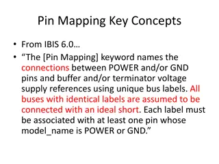
Green are the reserved pins for IO Devices Use Grey pins for GPIO The unassigned pins in schematic may use the grey pins right. JTAG Pins are allocated here: 5pin interface, in red.
BlueNRG-N schematic: Doesnt map properly to pinout of 232.
JTAG + I2C. Need SPI, but may conflict with JTAG, possible to use UART rather than SPI for host comms? See EVM Schematic For implementation details. VD_3p3 To be used as a co processor to the STM-32 C60 1n C62 1n C63 1n U22 25 24 NRG_RESETN RESETN VBAT1 19 VBAT2 15 16 18 6 28 ADC1 ADC2 FXTAL0 VBAT3 VDD1V2 FXTAL0, FXTAL1, DC voltage on XTAL pins -0.3 to +1.4 V NRG0 NRG1 17 26 14 C64 1n C65 1n FXTAL1 SMPSFILT1 ANATEST1 23 2 JTCK-SWTCK JTMS-SWTDIO SXTAL0 DIO9 22 31 1 32 SXTAL1 TEST DIO10 DIO11 30 DIO12 12 29 JTAG-TDI JTAG-TDO DIO0 DIO13 11 13 21 DIO1 DIO14/ANATEST0 10 DIO2 RF0 9 20 27 DIO3 RF1 8 I2C2_SCL DIO4 SMPSFILT2 7 I2C2_SDA DIO5 5 DIO6 4 DIO7/BOOT 3 33 DIO8 EXP BLUENRG-232
BlueNRG I/O SWCLK/SWDIO pins are defined, but not TDI/TDO?


