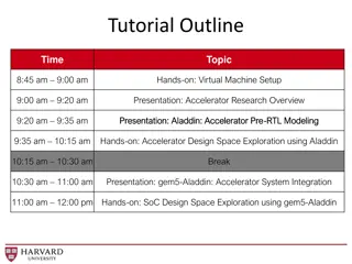
KEK Accelerator Workshop: Advancements in Collider Technology
KEK, Japan, has been at the forefront of e+e- colliders, pioneering technologies like crab cavity and achieving remarkable luminosity goals. The ongoing tradition continues with SuperKEKB, offering unique collision features and unprecedented beam currents. Addressing detector issues such as beam tails and non-gaussian backgrounds is crucial for maintaining high-quality data output in collider experiments.

Download Presentation

Please find below an Image/Link to download the presentation.
The content on the website is provided AS IS for your information and personal use only. It may not be sold, licensed, or shared on other websites without obtaining consent from the author. If you encounter any issues during the download, it is possible that the publisher has removed the file from their server.
You are allowed to download the files provided on this website for personal or commercial use, subject to the condition that they are used lawfully. All files are the property of their respective owners.
The content on the website is provided AS IS for your information and personal use only. It may not be sold, licensed, or shared on other websites without obtaining consent from the author.
E N D
Presentation Transcript
Machine Detector Interface Machine Detector Interface Issues Issues Mike Sullivan KEK Accelerator Workshop 2020 January 30-31 KEK, Japan 1
Outline Outline Introduction Detector Issues Beam Tails Machine Issues Other Issues Conclusion 2
Introduction Introduction KEK KEK has continuously pushed the frontier of e+e- colliders Tristan was the largest and highest energy collider until the SLC and LEP KEKB pioneered crab cavity technology and large angle collisions KEKB also set and achieved (x2!) a design goal of 1 1034 luminosity This was a very high number in the early 1990s SuperKEKB continues this tradition Very large angle collision (83 mrad) Nano-beam collision Lowest y* of any collider (1 mm) Design parameters 200 nm y* Lumi of 8 1035 Beam currents of 2.6 x 3.6 A These will be the highest colliding beam currents ever 3
Detector Features Detector Features Detector acceptance as large as possible Usually down to about 15 deg (300 mrad) Solenoidal magnetic field The large crossing angle complicates the beam trajectories in this field Small radius central beam pipe (1 cm) This means that vertex detectors are very close to the beam The final focus magnets are very close (actually inside) the detector 4
Some Detector Issues Some Detector Issues e- / e+ gas molecule Coulomb Beam Backgrounds Coulomb (elastic scattering) Beam-gas (inelastic scattering) Touschek (inter-bunch scattering) Luminosity related Beam-beam Non-gaussian beam tails The beam tail is generated by the above interactions as well as by other effects Non-gaussian beam tails can be quite large The e+ +e beams have very large damping terms from SR Collimation is necessary and crucial in order to control the above backgrounds as well as the SR background from the beam tail e- / e+ gas molecule BGB 5
More on detector backgrounds More on detector backgrounds Beam pipe scrubbing The SR from the electron and positron beams digs out the gas molecules imbedded in the beam pipe metal This generates gas pressure around the ring dynamic gas pressure which can be 10-100 times (or more!) higher than the zero-current base pressure Synchrotron Radiation is a major background from the beams Direct hits on the central beam pipe is the first concern These hits are usually coming from beam particles in the high sigma region where there is great uncertainty as to what the actual hit rate will end up being (More on this) The direct hit rate generally sets the radius of the central beam pipe Direct hits are much more difficult to mask out when the crossing angle is large High beam currents force us to worry about secondary scattering Forward as well as backward one bounce scattering In some cases tertiary (2 bounce photons) can be an issue if the source has a very high incident photon rate Usually these rates are not very high and can be ignored but too many hits from a single crossing can swamp a detector by making too much occupancy 6
Beam Tails Beam Tails The core of the beam is assumed gaussian in all 3 dimensions and we believe this is a good approximation However, any sort of interaction or perturbation of the beam particles can result in a beam particle getting out of this 3D gaussian distribution For electron (and positron) beams this out of the envelope beam particle, in many cases, has an excellent chance of damping back into the core distribution before it hits the dynamic aperture limit of the ring or hits a collimator and is lost Synchrotron radiation damping is very strong 7
Beam Tails (2) Beam Tails (2) What this essentially means is that sources of beam particle perturbation or interaction are constantly pushing beam particles out into the high beam sigma region (out into the non-gaussian tail) and SR is constantly pulling (damping) most of these particles back into the core distribution The result is a semi-stable distribution of beam particles out in the high sigma non-gaussian tail in all 3 dimensions The larger the dynamic aperture the more beam sigmas the particle can be in and still stay in the machine Machine designs strive to make the dynamic aperture as large as possible 8
Beam Tails (3) Beam Tails (3) Initially, during machine commissioning, the main sources of beam particle interaction are beam-gas collisions (this is the scrubbing phase) The luminosity is low, the tune shifts are low, the beam currents are low All beam pipes have gas molecules imbedded probably throughout the metal Baking out the vacuum chambers gets rid of the surface and near surface gas molecules and is very important (especially for water!) But the x-rays from the SR are much more penetrating and these photons will get to molecules that are deeper in the metal and give them the energy they need to migrate to the surface and outgas The outgassing rate decreases with time as the gas molecules embedded in the metal are gradually removed Remember that this applies to the entire inner beam pipe surface The strike surface of the SR beam cleans up fairly quickly but the scattered x-rays from the strike point must also clean up the rest of the beam pipe inner surface 9
Some Some Non Non- -gaussian gaussian Beam Tail Beam Tail Distributions Distributions Suggested early KEK beam tail Suggested early KEK beam tail Possible later beam tail Possible later beam tail The larger beam tail distribution has about 3.5% of the total particles of the bunch Gaussian Gaussian 10
Beam Tails (4) Beam Tails (4) As the initial outgassing diminishes and the beam lifetime increases the accelerator team can start raising the beam currents This, of course, increases the outgassing again and a balance must be struck to keep the backgrounds at an acceptable level for data taking As the currents increase so do the other beam particle perturbation terms The luminosity contribution increases as the lumi goes up (this one we want!!) The Touschek lifetime can drop increasing the background from this source Beam-beam effects become important Even beamstrahlung can become important As the machine performance improves the initial sources of non-gaussian particles diminishes but new sources become larger and more important So, there is always a non-gaussian beam tail distribution in the machine Especially in high current rings 11
Accelerator Issues Accelerator Issues High beam currents 2.6 A for the 7 GeV electron beam 3.6 A for the 4 GeV positron beam Short beam bunches ~6 mm HOM power around the ring Feedback systems Bunch-by-bunch orbit stability Transverse Longitudinal Luminosity Maintain the beams in collision with feedbacks Fast enough to compensate for final focus mechanical motion? 12
More Accelerator Issues More Accelerator Issues Clean injection Minimize detector background Maximize efficiency in order to keep up with short beam lifetimes Beam emittance Minimize orbit deviations in quadrupoles Control the dispersion functions Control the coupling Controls the vertical spot size Control beam size Beam blowup One beam blowing up the other beam Both beams blowing up from the collision Tunes Tune footprint 13
PEP-II HER tune plane PEP-II LER tune plane 14
More on accelerator issues More on accelerator issues Luminosity Low y* The accelerator team may discover they can go to lower y* or x* values. Then the y or x max is larger in the FF quads making more SR at larger distances from the beam axis in the FF quads. Continuous injection Low backgrounds Collimators can help here but clipping off too much injected beam can harm injection efficiency 15
Closely spaced beam bunches Closely spaced beam bunches When the bunch spacing gets close (~10 ns) the bunches can start to affect each other This is one of the main reasons the beam pipe must have smooth, gentle geometry transitions The PEP-II B-factory generally had a limit of 15 deg (1:12) for beam pipe transitions The left behind RF power can interact with the next bunch This bunch to bunch coupling must be controlled by feedback systems Smooth transitions minimize this impedance effect RF power S. Novokhatski has much better pictures of this effect 16
Some Conclusions Some Conclusions The accelerator and detector teams need to work closely together to maximize the efficiency of the commissioning phase The detector team wants to start taking data as soon as possible The accelerator team wants to move to the design machine as quickly as possible These goals sometimes need a bit of give and take Both teams eventually want the same thing high luminosity and data taking at the same time The beam tail distributions will change as the machine becomes better understood, as the scrubbing continues, and as the accelerator approaches the design parameters However, there will always be some form of non-gaussian tail distribution 17
Summary Summary These are exciting times! The SuperKEKB accelerator is truly a frontier machine Many features of this machine need to be better understood No one has such a machine to explore this part of accelerator parameter space What is discovered here will be used in all future collider designs 18


")
")

")