Kirchhoff's Laws and Circuit Properties
This lecture covers Kirchhoff's Current and Voltage Laws, explaining their application in analyzing circuits alongside Ohm's Law. Additionally, it delves into resistivity of materials, resistance calculations, Ohm's Law, short and open circuits. Explore how these fundamental concepts form the basis of circuit analysis.

Download Presentation

Please find below an Image/Link to download the presentation.
The content on the website is provided AS IS for your information and personal use only. It may not be sold, licensed, or shared on other websites without obtaining consent from the author. If you encounter any issues during the download, it is possible that the publisher has removed the file from their server.
You are allowed to download the files provided on this website for personal or commercial use, subject to the condition that they are used lawfully. All files are the property of their respective owners.
The content on the website is provided AS IS for your information and personal use only. It may not be sold, licensed, or shared on other websites without obtaining consent from the author.
E N D
Presentation Transcript
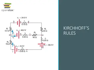
BLM1612 - Circuit Theory Prof. Dr. Nizamettin AYDIN naydin@yildiz.edu.tr Kirchhoff s Current Law Kirchhoff s Voltage Law 1
Objectives of the Lecture Present Kirchhoff s Current and Voltage Laws. Demonstrate how these laws can be used to find currents and voltages in a circuit. Explain how these laws can be used in conjunction with Ohm s Law. 2
Resistivity, Resistivity is a material property Dependent on the number of free or mobile charges (usually electrons) in the material. In a metal, this is the number of electrons from the outer shell that are ionized and become part of the sea of electrons Dependent on the mobility of the charges Mobility is related to the velocity of the charges. It is a function of the material, the frequency and magnitude of the voltage applied to make the charges move, and temperature. 3
Resistivity of Common Materials at Room Temperature (300K) Resistivity ( -cm) 1.64x10⁻⁸ 1.72x10⁻⁸ 2.8x10⁻⁸ 2.45x10⁻⁸ 4x10⁻⁵ 0.47 640 1010 5x10¹¹ 1012 3x10¹² Material Silver Copper Aluminum Gold Carbon (Graphite) Germanium Silicon Paper Mica Glass Teflon Usage Conductor Conductor Conductor Conductor Conductor Semiconductor Semiconductor Insulator Insulator Insulator Insulator 4
Resistance, R Resistance takes into account the physical dimensions of the material L = R A where: L is the length along which the carriers are moving A is the cross sectional areathat the free charges move through. 5
Ohms Law Voltage drop across a resistor is proportional to the current flowing through the resistor = v iR Units: V = A where A = C/s 6
Short Circuit If the resistor is a perfect conductor (or a short circuit) R = 0 , then v = iR = 0 V no matter how much current is flowing through the resistor 7
Open Circuit If the resistor is a perfect insulator, R = then no matter how much voltage is applied to (or dropped across) the resistor. 8
Conductance, G Conductance is the reciprocal of resistance G = R-1= i/v Unit for conductance is S (siemens) or (mhos, ) G = A /L where is conductivity, which is the inverse of resistivity, 9
Power Dissipated by a Resistor p = iv = i(iR) = i2R p = iv = (v/R)v = v2/R p = iv = i(i/G) = i2/G p = iv = (vG)v = v2G 10
Power Dissipated by a Resistor Since R and G are always real positive numbers Power dissipated by a resistor is always positive The power consumed by the resistor is not linear with respect to either the current flowing through the resistor or the voltage dropped across the resistor This power is released as heat. Thus, resistors get hot as they absorb power (or dissipate power) from the circuit. 11
Short and Open Circuits There is no power dissipated in a short circuit. = = = 2 2 v 0 ( V ) 0 ( ) 0 W psc R There is no power dissipated in an open circuit. = = = 2 2 i 0 ( A ) ( ) 0 W poc R 12
Circuit Terminology Node point at which 2+ elements have a common connection e.g., node 1, node 2, node 3 Path a route through a network, through nodes that never repeat e.g., 1 3 2, 1 2 3 Loop a path that starts & ends on the same node e.g., 3 1 2 3 Branch a single path in a network; contains one element and the nodes at the 2 ends e.g., 1 2, 1 3, 3 2 13
Exercise For the circuit below: a. Count the number of circuit elements. b. If we move from B to C to D, have we formed a path and/or a loop? c. If we move from E to D to C to B to E, have we formed a path and/or a loop? 14
Kirchhoffs Current Law (KCL) Gustav Robert Kirchhoff: German university professor, born while Ohm was experimenting Based upon conservation of charge the algebraic sum of the charge within a system can not change. the algebraic sum of the currents entering any node is zero. node node N = n = 0 i n 1 Where N is the total number of branches connected to a node. = enter i leave i 15
Kirchhoffs Voltage Law (KVL) Based upon conservation of energy the algebraic sum of voltages dropped across components around a loop is zero. The energy required to move a charge from point A to point B must have a value independent of the path chosen. = 1 m M = v 0 Where M is the total number of branches in the loop. = v v drops rises 16
Example-01 For the circuit, compute the current through R3 if it is known that the voltage source supplies a current of 3 A. Use KCL 17
Example-02 Referring to the single node below, compute: a. iB, given iA = 1 A, iD = 2 A, iC = 3 A, and iE = 4 A b. iE, given iA= 1 A, iB= 1 A, iC= 1 A, and iD= 1 A Use KCL iA+ iB- iC- iD- iE= 0 a. iB= -iA+ iC+ iD+ iE iB= -1 + 3 - 2 + 4 = 4 A b. iE= iA+ iB- iC- iD iE= -1 - 1 + 1 + 1 = 0 A 18
Example-03 Determine I, the current flowing out of the voltage source. Use KCL 1.9 mA + 0.5 mA + I are entering the node. 3 mA is leaving the node. 5 . 0 + + = 9 . 1 mA 3 mA = mA I 9 . 1 ( 5 . 0 + mA 3 ) I mA mA = 6 . 0 I mA V1 is generating power. 19
Example-04 Suppose the current through R2 was entering the node and the current through R3 was leaving the node. Use KCL 3 mA + 0.5 mA + I are entering the node. 1.9 mA is leaving the node. 5 . 0 + + 9 . 1 = mA 3 = mA I mA 5 . 0 + 9 . 1 = 3 ( ) I mA mA mA 6 . 1 I mA V1 is dissipating power. 20
Example-05 If voltage drops are given instead of currents, you need to apply Ohm s Law to determine the current flowing through each of the resistors before you can find the current flowing out of the voltage supply. I1is leaving the node. I2is entering the node. I3is entering the node. I is entering the node. I2 I3 I1 = = 2 / 7 . 0 = 286 I V 4 k mA 1 = / 2 2 I V 75 k / mA . 0 = + + = I 2 I I 35 I 2 2 3 1 . 1 = 5 35 I V k mA + + = . 0 . 0 286 = mA = mA I mA . 2 3 . 0 286 . 2 35 06 I mA mA mA 21
Example-06 For each of the circuits in the figure below, determine the voltage vxand the current ix. Applying KVL clockwise around the loop and Ohm s law 22
Example-07 For the circuit below, determine a. vR2 b. vx a. b. 23
Example-08 For the circuit below, determine a. vR2 b. vx if vR1 = 1 V. a. b. 24
Example-09 For the circuit below, determine vx 25
Example-10 Find the voltage across R1. Note that the polarity of the voltage has been assigned in the circuit schematic. First, define a loop that include R1. 26
Example-10 If the red loop is considered By convention, voltage drops are added and voltage rises are subtracted in KVL. 5 V VR1+ 3 V = 0 VR1 = -2 V 27
Example-10 Suppose you chose the green loop instead. Since R2 is in parallel with I1, the voltage drop across R2 is also 3V. 5 V VR1+ 3 V = 0 VR1 = -2 V 28
Example-11 Find the voltage across R2 and the current flowing through it. First, draw a loop that includes R2. 29
Example-11 If the green loop is used: 11.5 V + 2.4 V + VR2= 0 VR2 = 9.1 V 30
Example-11 If the blue loop is used: First, find the voltage drop across R3 1 mA 1.1 k = 1 10-3 A 1.1 103 = 1.1 V 1.1 V + 8 V - VR2= 0 VR2 = 9.1 V 31
Example-11 Once the voltage across R2 is known, Ohm s Law is applied to determine the current. IR2 IR2 = 9.1 V / 4.7 k = 9.1 V / (4.7 103 ) IR2 = 1.94 10-3 A = 1.94 mA 32


")


")
")