Labeling Guidelines for Technical Drawings
When creating technical drawings, it's crucial to follow specific labeling guidelines for clarity and precision. Ensure each view is properly labeled in capital letters, centered beneath the view. Include symbols like 3rd Angle Projection, Radius, Diameter, and follow proper dimension ordering. Add necessary information like drawing title, your name, and the drawing date. Remember to include center lines manually if using software that doesn't automate this. Additional details like material thickness and drawing scale should also be indicated on the page.

Download Presentation

Please find below an Image/Link to download the presentation.
The content on the website is provided AS IS for your information and personal use only. It may not be sold, licensed, or shared on other websites without obtaining consent from the author.If you encounter any issues during the download, it is possible that the publisher has removed the file from their server.
You are allowed to download the files provided on this website for personal or commercial use, subject to the condition that they are used lawfully. All files are the property of their respective owners.
The content on the website is provided AS IS for your information and personal use only. It may not be sold, licensed, or shared on other websites without obtaining consent from the author.
E N D
Presentation Transcript
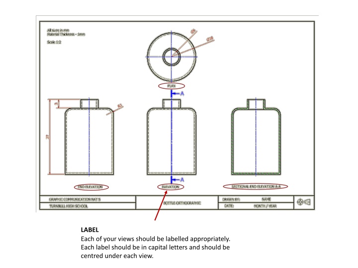
LABEL Each of your views should be labelled appropriately. Each label should be in capital letters and should be centred under each view.
3RD ANGLE PROJECTION SYMBOL This is only necessary when you have drawn an orthographic drawing to show which way the views are projected. DRAWING TITLE Your drawing should be named appropriately to describe what the drawing is showing e.g. Assembled orthographic, exploded isometric etc. NAME AND DATE You should include your name and when the drawing was produced.
RADIUS The radius symbol should only be used when dimensioning curves and arcs. It should never be used for dimensioning a complete circle. DIAMETER The diameter symbol should be used when dimensioning full circles. DIMENSION ORDERING Larger dimensions should be placed further away from the object while smaller dimensions should be placed closer to the object.
Centre Lines Centre lines are not automatically added in Inventor so you must add them yourself.
ADDITIONAL INFO Additional information such as the thickness of the material (if applicable) and the scale of the drawing should be added to the page.