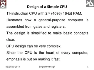
Lecture 15: Basic CPU Design
Explore examples of Finite State Machines (FSM) in CPU design, covering single-cycle and multi-cycle CPUs. Learn about state diagrams, tackling FSM problems, a residential thermostat example, latch vs. flip-flop comparison, and basic MIPS architecture concepts.

Download Presentation

Please find below an Image/Link to download the presentation.
The content on the website is provided AS IS for your information and personal use only. It may not be sold, licensed, or shared on other websites without obtaining consent from the author.If you encounter any issues during the download, it is possible that the publisher has removed the file from their server.
You are allowed to download the files provided on this website for personal or commercial use, subject to the condition that they are used lawfully. All files are the property of their respective owners.
The content on the website is provided AS IS for your information and personal use only. It may not be sold, licensed, or shared on other websites without obtaining consent from the author.
E N D
Presentation Transcript
Lecture 15: Basic CPU Design Today s topics: FSM examples Single-cycle CPU Multi-cycle CPU 1
State Diagram State Transition Table: CurrState InputEW InputNS NextState=Output N 0 0 N N 0 1 N N 1 0 E N 1 1 E E 0 0 E E 0 1 N E 1 0 E E 1 1 N 2 Source: H&P textbook
Tackling FSM Problems Three questions worth asking: What are the possible output states? Draw a bubble for each. What are inputs? What values can those inputs take? For each state, what do I do for each possible input value? Draw an arc out of every bubble for every input value. 3
Example Residential Thermostat Two temp sensors: internal and external If internal temp is within 1 degree of desired, don t change setting If internal temp is > 1 degree higher than desired, turn AC on; if internal temp is < 1 degree lower than desired, turn heater on If external temp and desired temp are within 5 degrees, disregard the internal temp, and turn both AC and heater off 4
Finite State Diagram U-H U-C, U-G U-H, U-G HEAT COOL U-C U-C U-H D-C, D-G, D-H D-C, D-G, D-H Int temp settings: C cold G goldilocks H hot OFF Ext temp settings: D desired zone U undesired zone D-C, D-G, D-H, U-G 6
Latch vs. Flip-Flop Recall that we want a circuit to have stable inputs for an entire cycle so I want my new inputs to arrive at the start of a cycle and be fixed for an entire cycle A flip-flop provides the above semantics (a door that swings open and shut at the start of a cycle) But a flip-flop needs two back-to-back D-latches, i.e., more transistors, delay, power You can reduce these overheads with just a single D-latch (a door that is open for half a cycle) as long as you can tolerate stable inputs for just half a cycle 7
Basic MIPS Architecture Now that we understand clocks and storage of states, we ll design a simple CPU that executes: basic math (add, sub, and, or, slt) memory access (lw and sw) branch and jump instructions (beq and j) 8
Implementation Overview We need memory to store instructions to store data for now, let s make them separate units We need registers, ALU, and a whole lot of control logic CPU operations common to all instructions: use the program counter (PC) to pull instruction out of instruction memory read register values 9
View from 30,000 Feet Note: we haven t bothered showing multiplexors Source: H&P textbook What is the role of the Add units? Explain the inputs to the data memory unit Explain the inputs to the ALU Explain the inputs to the register unit 10
View from 30,000 Feet Note: we haven t bothered showing multiplexors Source: H&P textbook What is the role of the Add units? Explain the inputs to the data memory unit Explain the inputs to the ALU Explain the inputs to the register unit 11
Clocking Methodology Source: H&P textbook Which of the above units need a clock? What is being saved (latched) on the rising edge of the clock? Keep in mind that the latched value remains there for an entire cycle 12
Implementing R-type Instructions Instructions of the form add $t1, $t2, $t3 Explain the role of each signal Source: H&P textbook 13
Implementing Loads/Stores Instructions of the form lw $t1, 8($t2) and sw $t1, 8($t2) Where does this input come from? 14 Source: H&P textbook
Implementing Loads/Stores Instructions of the form lw $t1, 8($t2) and sw $t1, 8($t2) Where does this input come from? 15 Source: H&P textbook
Implementing J-type Instructions Instructions of the form beq $t1, $t2, offset Source: H&P textbook 16
View from 10,000 Feet 17 Source: H&P textbook
View from 5,000 Feet 18 Source: H&P textbook
Latches and Clocks in a Single-Cycle Design Instr Mem Reg File Data Memory PC ALU Addr The entire instruction executes in a single cycle Green blocks are latches At the rising edge, a new PC is recorded At the rising edge, the result of the previous cycle is recorded At the falling edge, the address of LW/SW is recorded so we can access the data memory in the 2nd half of the cycle 19