Lecture Class Slide Presentation 3-31-2020
Delve into the use of International Tolerance zones and ISO Limits in engineering drawing assignments. Learn how to apply fits and tolerances using ISO standards and tables. Explore concepts like Press Fits, Push Fits, and Nominal Sizes in practical design scenarios. Complete the given class assignment on ball bearing fits to enhance your understanding of mating parts design.

Download Presentation

Please find below an Image/Link to download the presentation.
The content on the website is provided AS IS for your information and personal use only. It may not be sold, licensed, or shared on other websites without obtaining consent from the author.If you encounter any issues during the download, it is possible that the publisher has removed the file from their server.
You are allowed to download the files provided on this website for personal or commercial use, subject to the condition that they are used lawfully. All files are the property of their respective owners.
The content on the website is provided AS IS for your information and personal use only. It may not be sold, licensed, or shared on other websites without obtaining consent from the author.
E N D
Presentation Transcript
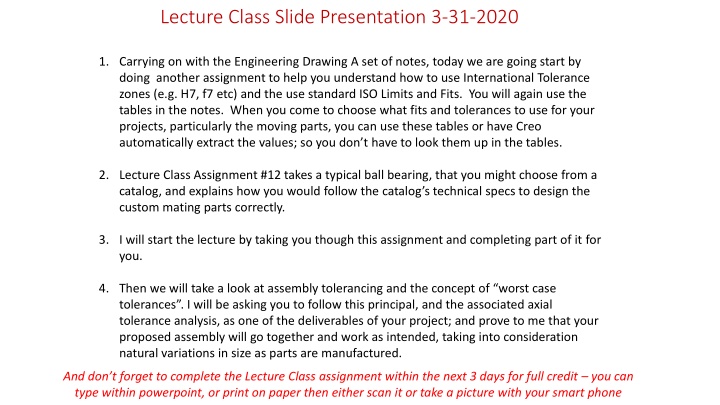
Lecture Class Slide Presentation 3-31-2020 1. Carrying on with the Engineering Drawing A set of notes, today we are going start by doing another assignment to help you understand how to use International Tolerance zones (e.g. H7, f7 etc) and the use standard ISO Limits and Fits. You will again use the tables in the notes. When you come to choose what fits and tolerances to use for your projects, particularly the moving parts, you can use these tables or have Creo automatically extract the values; so you don t have to look them up in the tables. 2. Lecture Class Assignment #12 takes a typical ball bearing, that you might choose from a catalog, and explains how you would follow the catalog s technical specs to design the custom mating parts correctly. 3. I will start the lecture by taking you though this assignment and completing part of it for you. 4. Then we will take a look at assembly tolerancing and the concept of worst case tolerances . I will be asking you to follow this principal, and the associated axial tolerance analysis, as one of the deliverables of your project; and prove to me that your proposed assembly will go together and work as intended, taking into consideration natural variations in size as parts are manufactured. And don t forget to complete the Lecture Class assignment within the next 3 days for full credit you can type within powerpoint, or print on paper then either scan it or take a picture with your smart phone
Context of this weeks lecture class assignment Purchased bearings (off- the-shelf) for a new roller blade design. What tolerances to put on the mating parts? Roller Blade Assembly Model Exploded View of Roller Blade Assembly
I have copied the assignment to the right here so that I can refer to it. And labeled the key parts that: Lecture Class Assignment #12 Tolerances Ball Bearing fits Shaft Diameter Ball Bearing (8mm I/D x 22mm O/D) 1. Determine the fit between the shaft and the ID (inside diameter) of the bearing. 2. Determine the fit between the OD (outside Diameter) of the ball bearing and the Housing Housing Diameter The bearing is purchased with a tolerance. When you purchase a part like this, the manufacturer will include the tolerances of the part in the specifications so that design engineers, like you, know what to expect. They will generally also tell you what fit is required for the device to perform as designed. These fits for 1. and 2. above are specified as: 1. An ISO Press Fit 2. An ISO Push Fit The Ball Bearing specifications say that it should be assembled into the housing with an ISO Push Fit and that the shaft should be inserted with an ISO Press Fit 1. Specify the dimensions for the shaft diameter (in ISO bilateral form): 2. Specify the dimensions for housing diameter (also in bilateral form): These fits are described in the following slide:
ISO Interference Fits Press Fit Drive Fit ISO Standard "Hole Basis Transition Fits Nominal Sizes Tolerance Tolerance Over mm To mm H7 p6 H7 s6 0.001 mm 0.001 mm 0.001 mm 0.001 mm +10 0 +12 0 +15 0 +18 0 +21 0 +12 +6 +20 +12 +24 +15 +29 +18 +35 +22 +10 0 +12 0 +15 0 +18 0 +21 0 +20 +14 +27 +19 +32 +23 +39 +28 +48 +35 Type of Fit Hole Shaft H7 3 3 6 Locational Transition Fits. for accurate location, a compromise between clearance and interference Push Fits. Transition fits averaging little or no clearance and are recommended for location fits where a slight interferance can be tolerated for the purpose, for example, of eliminating vibration. k6 6 10 10 18 18 30 H7 n6 30 40 +25 0 +42 +26 +25 0 +59 +43 40 50 +30 0 +30 0 +35 0 +35 0 +40 0 +40 0 +40 0 +46 0 +46 0 +46 0 +52 0 +52 0 +57 0 +57 0 +63 0 +63 0 +72 +53 +78 +59 +93 +78 +101 +79 +117 +92 +125 +100 +133 +108 +151 +122 +159 +130 +169 +140 +198 +158 +202 +170 +226 +190 +244 +208 +272 +232 +292 +252 50 65 +30 0 +51 +32 65 80 80 100 +35 0 +59 +37 100 120 ISO Standard "Hole Basis" Interference Fits 120 140 +40 0 +68 +43 140 160 160 180 Type of Fit Hole Shaft H7 180 200 +46 0 +79 +50 200 225 Press Fit. Suitable as the standard press fit into ferrous, i.e. steel, cast iron etc., assemblies. Drive Fit Suitable as press fits in material of low modulus of elasticity such as light alloys. p6 225 250 250 280 +52 0 +88 +56 H7 s6 280 315 315 355 +57 0 +98 +62 355 400 Slide 66 of Engineering Drawing A notes 400 450 +63 0 +108 +68 Slide 63 of Engineering Drawing A notes 450 500
So, heres the answer to the 1st part: 1. Specify the dimensions for the shaft diameter (in ISO bilateral form): Lecture Class Assignment #12 Tolerances Ball Bearing fits Shaft Diameter This is in quotes because its probably not really what you would think of as the shaft in this assembly, however, in the context of standard Limits and Fits the tables, whether ANSI or ISO, uses the terms Shaft to describe the part to be inserted INTO the receiving part or Hole . Ball Bearing (8mm I/D x 22mm O/D) In this ball bearing assembly, the black nylon sleeve is the shaft as it inserted into the ID of the bearing, the hole of the bearing. Housing Diameter Referring to the previous slide, we see that for the specified ISO Press Fit , the hole should be an H7 and the shaft should be a p6 (note: holes always use uppercase (i.e. H here) and shafts always use lowercase (i.e. p here) The Ball Bearing specifications say that it should be assembled into the housing with an ISO Push Fit and that the shaft should be inserted with an ISO Press Fit The hole is the ID of the bearing and we can assume that it was manufactured to the H7 required by the fit. The shaft is also the diameter of the bearing but required to be p6, for the bearing to perform correctly. I have circled the relevant row and column data that provide the answer shown here. Follow the same logic to complete 2.- same format ( ) + 0.024 + 0.015 1. Specify the dimensions for the shaft diameter (in ISO bilateral form): 8 p6 2. Specify the dimensions for housing diameter (also in bilateral form):
Tolerance Calculation - 'Worst Case Method' for correct fit in all cases, if manufactured to specification Allowance The minimum allowable difference between mating parts: Allowance = Smallest Hole Size - Largest Shaft Size Clearance The maximum allowable difference between mating parts: Clearance = Largest Hole Size - Smallest Shaft Size The 'Tolerance Build-up Problem' Where the combined dimension of several mating parts results in an unacceptable condition: generally non-functional (e.g. rotating or sliding action impaired), or parts will not assemble, or aesthetically unacceptable (e.g. inconsistent gaps around car doors) 'Shaft in hole' Terminology Shaft Hole
Worst Case Tolerance Example Shaft in Hole B A Clearance = Largest Hole Size (A) Smallest Shaft Size (B) Allowance = Smallest Hole Size (A) Largest Shaft Size (B) A For example: If the nominal dimension is 10mm and general tolerance invoked i.e. feature A and B (Hole & Shaft) are both: (i.e. overall tolerance of 0.25 mm) + 0.125 - 0.125 10 Then, Clearance = 10.125 9.875 = 0.25 Allowance = 9.875 10.125 = - 0.25 * Lid on Box * A negative in the result means interference General Tolerance +/- 0.125 unless otherwise specified All units in mms B
Use Specific Tolerances as required but keep overall tolerance as loose as possible for function/aesthetic + 0.000 - 0.125 + 0.125 - 0.000 10 10 Clearance = Largest Hole Size (A) Smallest Shaft Size (B) Allowance = Smallest Hole Size (A) Largest Shaft Size (B) + 0.125 - 0.000 10 So, Clearance = 10.125 9.875 = 0.25 Allowance = 10 10 = 0 No negative therefore no interference even in worst case , so lid will fit on the box relatively easily in all designed conditions. Lid on Box General Tolerance +/- 0.125 unless otherwise specified All units in mms + 0.000 - 0.125 10
Name: Solution Lecture Class Assignment XXX- Worst Case Tolerance - Block and Carrier Blocks A B + + 0.2 0.2 B A Carrier Clearance = Largest Hole Smallest Shaft Allowance = Smallest Hole Largest Shaft Largest Hole = 4.8 Smallest Shaft = 1.8 + 1.8 = 3.6 + + 0.8 + + 0.4 A B Clearance = 4.8 3.6 = 1.2 Smallest hole = 4.4 Largest shaft = 2.2 + 2.2 = 4.4 A B Allowance = 4.4 4.4 = 0 1. What is the clearance between the between the blocks and the carrier _______1.2_____ 2. What is the allowance between the blocks and the carrier ______0_____