Linear Dark Band Artifact in Intrinsic Uniformity QC Imaging
Explore the cause of a linear dark band artifact on the left side of the Intrinsic Uniformity QC image for Detector 1 in a SPECT/CT system. The artifact is a result of an external source of radiation being partially blocked by the edge of the camera crystal. Learn how contaminated waste and camera head orientation contributed to this issue.

Download Presentation

Please find below an Image/Link to download the presentation.
The content on the website is provided AS IS for your information and personal use only. It may not be sold, licensed, or shared on other websites without obtaining consent from the author. If you encounter any issues during the download, it is possible that the publisher has removed the file from their server.
You are allowed to download the files provided on this website for personal or commercial use, subject to the condition that they are used lawfully. All files are the property of their respective owners.
The content on the website is provided AS IS for your information and personal use only. It may not be sold, licensed, or shared on other websites without obtaining consent from the author.
E N D
Presentation Transcript
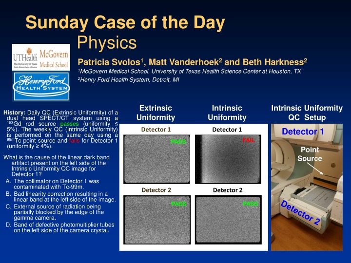
Sunday Case of the Day Physics Patricia Svolos1, Matt Vanderhoek2 and Beth Harkness2 1McGovern Medical School, University of Texas Health Science Center at Houston, TX 2Henry Ford Health System, Detroit, MI Extrinsic Uniformity Intrinsic Uniformity Intrinsic Uniformity QC Setup History: Daily QC (Extrinsic Uniformity) of a dual head SPECT/CT system using a 153Gd rod source passes (uniformity 5%). The weekly QC (Intrinsic Uniformity) is performed on the same day using a 99mTc point source and fails for Detector 1 (uniformity 4%). Detector 1 Detector 1 Detector 1 FAIL PASS Point Source What is the cause of the linear dark band artifact present on the left side of the Intrinsic Uniformity QC image for Detector 1? A. The collimator on Detector 1 was contaminated with Tc-99m. B. Bad linearity correction resulting in a linear band at the left side of the image. C. External source of radiation being partially blocked by the edge of the gamma camera. D. Band of defective photomultiplier tubes on the left side of the camera crystal. Detector 2 Detector 2 PASS PASS
Diagnosis:C. External source of radiation being partially blocked by the edge of the camera crystal. Intrinsic QC is performed without the collimators on the system. Contaminated waste in the trash was in the room during QC testing. The 180o orientation of the camera heads was such that Detector 1 faced down toward the floor while Detector 2 faced up toward the ceiling. Consequently, the contaminated trash (on the floor) irradiated the face of Detector 1 (yellow lines) but not the face of Detector 2. Photons were attenuated at certain angles by the leaded light rail on Detector 1, thus creating a linear shadow of the light rail on the edge of the acquired uniformity image. Detector 1
Discussion: A. The collimator on Detector 1 was contaminated with Tc-99m Incorrect Collimators are used only during extrinsic uniformity QC. Collimator contamination of Detector 1 with Tc-99m would likely result in an artifact on the extrinsic uniformity QC image with a random pattern (looking more splotchy ) rather than a linear dark band artifact. The acquired extrinsic uniformity image for Detector 1 was free of such artifacts.
Discussion:B. Bad linearity correction resulting in a linear band at the left side of the image Incorrect Artifacts due to bad linearity correction usually have a tubular pattern rather than linear. Image below shows a typical artifact pattern of all PMT being visible if linearity correction fails.
Discussion:D. Band of defective photomultiplier tubes on the left side of the camera crystal Incorrect It is unlikely that a set of defective photomultiplier tubes near the edge of the crystal would result in a linear dark band artifact. Image below shows a typical artifact due to bad photomultiplier tubes.
References/Bibliography: 1. Physics in Nuclear Medicine. Cherry S.R., Sorenson J.A., Phelps M.E.


