Linear vs. Switching Voltage Regulators - Types and Comparison
Discover the differences between linear and switching voltage regulators, including their designs, efficiencies, costs, sizes, and more. Learn about dropout voltage and how it affects regulator performance. Explore the advantages and disadvantages of each type to make informed decisions for your electronic projects.

Download Presentation

Please find below an Image/Link to download the presentation.
The content on the website is provided AS IS for your information and personal use only. It may not be sold, licensed, or shared on other websites without obtaining consent from the author. If you encounter any issues during the download, it is possible that the publisher has removed the file from their server.
You are allowed to download the files provided on this website for personal or commercial use, subject to the condition that they are used lawfully. All files are the property of their respective owners.
The content on the website is provided AS IS for your information and personal use only. It may not be sold, licensed, or shared on other websites without obtaining consent from the author.
E N D
Presentation Transcript
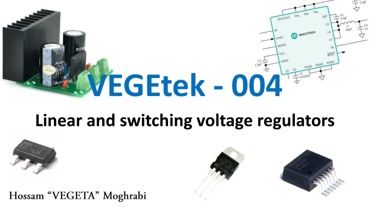
VEGEtek - 004 Linear and switching voltage regulators
Voltage regulators A voltage regulator is a device, IC, or circuit that outputs a fixed voltage to it s loads. For example, a 5v regulator outputs 5v to the loads which can be 100 Ohms which will result in 50mA of current. Each regulator has its own limitation in terms of current and total power. Types of voltage regulators Basically 2 main types: linear and switching. Each of them has its own advantages and disadvantages, as well as, field of application. Both types has an electronic switch (transistor) as well as other elements. The main difference is the utilization of this transistor element in each topology. 1
Linear regulator Figure 1 shows the typical linear regulator, the transistor here is called pass element which is delivering power continuously to the load. The transistor here can be BJT or MOSFET and it will be operating in the linear region . Figure 1: linear voltage regulator basic schematic A feedback signal and a reference signal is compared together using an error amplifier (Op-amp), which in turns controls the transistor to keep it s output voltage stable. 2
Switching regulator Figure 2 shows the typical switching regulator, the transistor here is called switching element which is connecting and disconnecting input power to the load. The transistor here can be BJT or MOSFET and it will be operating in the saturation or cut off region. Figure 2: switching voltage regulator (boost) schematic Switching regulators have an energy storage element to store energy and discharge it continuously. Thus power is in a form of pulses in the transistor not a continuous flow of current. 3
Comparison between linear and switching regulators Criteria linear regulator Switching regulator Design complexity Low Mid to high Efficiency Low and thus big heat dissipation High Cost Low Higher than linear Size Small Big with much more components Noise Low High due to switching effect Range conversion Only step-down Step up, down, and inverting Isolation No Yes Dropout voltage: it is the voltage difference between input and output voltage. It is what determines the efficiency of the linear regulator. LDOs are low dropout regulators which operates at a very low dropout such as 1v. Example: input voltage = 10v, output voltage = 7v, and 1A of current will have 3v dropout (10-7). Thus the wasted power in the transistor of the linear regulator is 3v * 1A = 3W which is too much. Efficiency is 7W/10W = 0.7 = 70%, while similar switching regulator of the same specs can easily reach 95%. Many linear regulators do not have such low dropout like regulating 12v to 5v (at 2A) which has ~ 41.7% efficiency. Heatsinks are a must in most linear regulators. 4
Types of linear regulators Depends on the pass element used, which determines the dropout voltage and stability. NPN (and Darlington NPN) Quasi regulator PNP (LDO regulator) P-MOSFET regulator N-MOSFET regulator 5
Types of switching regulators Depends on the arrangement of the elements in the circuit and control signals. SEPIC topology There are other topologies like fly-back (which offers isolation), Cuk, forward, push-pull, etc. 6
Hybrid regulators These are circuits which combines both switching and linear regulators. Linear regulator is the final output regulator while the switching one is before it so that the switching one provides the linear one with an input of the output voltage + a small dropout to enhance efficiency while keeping the useful and clean linear regulator output. Such switching regulators are called Pre-regulators and the linear regulators are sometimes called Post-regulators . It is a relatively new method in power supplies to gain high efficiency and low dropout at the same time. The pre- regulators might be controlled by a feedback from the linear output voltage, in this case the switching regulator is called tracking pre-regulator . Figure 2 below shows an example of the hybrid regulator. Figure 2: hybrid regulator 7


