Link Level Simulation Assumptions for 3GPP TSG-RAN Meeting #99-e
Summary of link level simulation assumptions discussed at the 3GPP TSG-RAN WG4 Meeting #99-e, covering parameters like carrier frequency, modulation schemes, HARQ processes, antenna configurations, and simulation results for 1024QAM in NR. Related contributions from Ericsson, Nokia, ZTE, and Huawei also highlighted.
Download Presentation

Please find below an Image/Link to download the presentation.
The content on the website is provided AS IS for your information and personal use only. It may not be sold, licensed, or shared on other websites without obtaining consent from the author.If you encounter any issues during the download, it is possible that the publisher has removed the file from their server.
You are allowed to download the files provided on this website for personal or commercial use, subject to the condition that they are used lawfully. All files are the property of their respective owners.
The content on the website is provided AS IS for your information and personal use only. It may not be sold, licensed, or shared on other websites without obtaining consent from the author.
E N D
Presentation Transcript
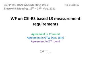
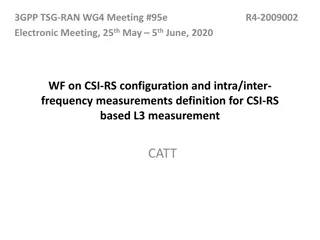
3GPP TSG-RAN WG4 Meeting #99-e R4-2108633 Electronic Meeting, May. 19 27, 2021 WF on Link level simulation WF on Link level simulation assumptions assumptions CATT
Summary of link simulation assumptions Parameter Carrier frequency CBW SCS Value 2 GHz 40MHz 15kHz Allocated RBs Full allocation TDL-A 10ns delay spread, Maximum Doppler frequency: 5Hz TDL-D 10ns delay spread, Maximum Doppler frequency: 5Hz 256QAM: MCS 24 in TS 38.214 Table 5.1.3.1-2: MCS index table 2 for PDSCH, and other MCSs are not precluded 1024QAM: MCS 24 in the following Table according to the agreement in RAN1 #104, and other MCSs are not precluded Propagation MCS Modulation Target Spectral Index Order code Rate R x MCS IMCS Qm efficiency [1024] 23 10 805.5 7.8662 24 10 853 8.3301 25 10 900.5 8.7939 26 10 948 9.2578 Precoding Precoding configuration defined in 38.101-4 Section 7.2 for fading channels; follow PMI Symbol type CP-OFDM
Summary of link simulation assumptions Parameter Number of HARQ transmission RV sequence RANK Value 8 HARQ processes, maximum 4 transmissions {0,2,3,1} One and Two Option 1: 1 and 2 Option 2: 8 4 BS antennaconfiguration UE antennaconfiguration Antennacorrelation (Tx and Rx) Channel estimation Low correlation Practical Option 1: MMSE Option 2: MMSE-IRC Type A mapping, Start symbol 1, Duration 13 (for D slots) Receiver type PDSCH configuration DMRS configuration DMRS type : Type 1, Single symbol, additional DM-RS (dmrsAdditionalPosition): pos1 txEVM 2%, 2.5%, 3% To be added. rxEVM
Related contributions R4-2108692, Email discussion summary for [99-e][311] NR_DL1024QAM_BSRF, Moderator (Ericsson) R4-2109111, Link level simulation results for 1024QAM for NR FR1, CATT, RAN4#99-e R4-2110141, 1024QAM simulation assumptions and preliminary results, Nokia, Nokia Shanghai Bell, RAN4#99-e R4-2110606, Initial simulation results for NR 1024QAM, ZTE Corporation, RAN4#99-e R4-2110663, Link simulation for support of 1024QAM, Huawei, HiSilicon, RAN4#99-e R4-2110482, Link Simulation Results for BS EVM, Ericsson, RAN4#99-e
