Link Transmit Power for Improved Transceiver Performance
Enhance transceiver performance by adjusting transmit power per link direction, aligning with receiver capabilities, channel conditions, and more. This proposal suggests modifying transmit power per link to surpass existing EVM requirements, supported by simulation results and measurements. The introduction of Link Transmit Power (LTP) signaling enables adjustments for higher MCS use and system-wide spatial reuse, benefiting modern receivers and potential future improvements in receiver design.
Download Presentation

Please find below an Image/Link to download the presentation.
The content on the website is provided AS IS for your information and personal use only. It may not be sold, licensed, or shared on other websites without obtaining consent from the author. If you encounter any issues during the download, it is possible that the publisher has removed the file from their server.
You are allowed to download the files provided on this website for personal or commercial use, subject to the condition that they are used lawfully. All files are the property of their respective owners.
The content on the website is provided AS IS for your information and personal use only. It may not be sold, licensed, or shared on other websites without obtaining consent from the author.
E N D
Presentation Transcript
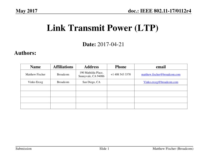
May 2017 doc.: IEEE 802.11-17/0112r4 Link Transmit Power (LTP) Date: 2017-04-21 Authors: Name Affiliations Address Phone email 190 Mathilda Place, Sunnyvale, CA 94086 Matthew Fischer Broadcom +1 408 543 3370 matthew.fischer@broadcom.com Vinko Erceg Broadcom San Diego, CA Vinko.erceg@broadcom.com Submission Slide 1 Matthew Fischer (Broadcom)
May 2017 doc.: IEEE 802.11-17/0112r4 Abstract Transceivers can benefit from increased EVM when compared to EVM requirements in the spec Due to Tx Beamforming, delay spread, Doppler, receiver design, expected variation in operating conditions, e.g. temperature, voltage, ageing, etc. Existing EVM spec targeted to SISO, CDD We show both simulation results and measurement data to justify our proposal Proposal provides a means for TX Power modification per link Per request of the recipient and approval of the transmitter Signaling through elements and management frames Slide 2 Submission Matthew Fischer (Broadcom)
May 2017 doc.: IEEE 802.11-17/0112r4 CID 8098 Add a mechanism to set the transmit power per direction per link in order to achieve an increase in performance due to improved receiver design since the original EVM specification was written. Add a mechanism to set the transmit power per direction per link in order to achieve an increase in performance due to improved receiver design since the original EVM specification was written. Expect a submission detailing some changes. Submission Slide 3 Matthew Fischer (Broadcom)
May 2017 doc.: IEEE 802.11-17/0112r4 Rationale Reasons to expect that EVM can be increased over EVM in the spec: LDPC requires less stringent EVM requirements TX EVM varies over operating condition, but TX PA set for worst case Beamforming (NTX > NSS) accommodates relaxed EVM TX Power is typically conservative due to implementation variance and measurement precision Channel delay spread is not known at transmitter Doppler is not known at transmitter TX EVM defined in standard was low bar for receiver design expectations a few years ago Modern receivers can typically handle increased EVM due to LDPC, etc. Additional receiver design improvements are likely in the future TX EVM defined in standard was based on SISO, CDD Submission Slide 4 Matthew Fischer (Broadcom)
May 2017 doc.: IEEE 802.11-17/0112r4 LTP Benefits Link Transmit Power signaling closes the loop with the receiver Allowing accuracy in TX Power setting to match (or exceed) TX EVM, receiver capability, channel condition, etc, which transmitter cannot determine Link Transmit Power signaling mechanism allows: Increase in TX Power per MCS to allow higher MCS use Reduction in TX Power to aid in system wide spatial reuse Submission Slide 5 Matthew Fischer (Broadcom)
May 2017 doc.: IEEE 802.11-17/0112r4 Transmitter Self Adjustment Transmitter may be able to make TX power adjustments to account for: Precoding Scenario (8x2, 4x2, 2x2, using beamforming or spatial expansion) PA characteristic, e.g. non-linearity, with margin for uncertainty in measurement and for dynamic operating condition changes, e.g. voltage, temperature, ageing A typical implementation shows an average of 1.5 dB of margin However, transmitter cannot make adjustments to account for channel condition (Doppler and Delay Spread) and receiver characteristics Receiver can measure channel effect and request power increase or decrease to optimize link and system gain Submission Slide 6 Matthew Fischer (Broadcom)
May 2017 doc.: IEEE 802.11-17/0112r4 Simulation Conditions, Gain Metric TSIM = Theoretical simulation model, not an architectural model E.g. ideal channel estimates, floating point math PA simulated is lab measured Skyworks PA (SKY85302-11) Using Channel B NLOS 80MHz, and D NLOS 80MHz For NSS=2: tested scenarios are Precoding NTX=4 x NRX=2 and NTX=8 x NRX=2. For NSS=1: tested scenarios are Precoding NTX=4 x NRX=2 and NTX=8 x NRX=2. Reference scenario is nominal OBO: power that yields standard specified TX EVM with 1.5dB margin. 1.5 dB margin based on practical Tx power accuracy used in APs For each scenario we mark the OBO which optimizes link budget for 10% PER The optimal OBO is achievable in a closed loop system that controls Tx power based on measured distortion at the receiver The difference between the optimal OBO and nominal OBO minus the sensitivity change is the LTP gain we could achieve by letting receiver request transmit power. Submission Slide 7 Matthew Fischer (Broadcom)
May 2017 doc.: IEEE 802.11-17/0112r4 Simulation Configuration NTX=4 and NRX=2 Channel configured for an average attenuation of 0dB A particular channel draw can have different attenuation Receiver noise power, PRX_NOISE , is fixed for a desired SNR range around sensitivity Using the predefined average channel attenuation Receiver signal power, PRX, is random according the channel draw Beamforming gain depends on channel draw too The simulation sweeps on transmitted power PTX , at a given OBO and finds the PER threshold of 10% Actually, the channel is considered as black box and the simulation controls PTX(OBO) and PRX_NOISE PRX_NOISE PTX PTX PTX PTX PRX + Channel PRX + PRX_NOISE Submission Slide 8 Matthew Fischer (Broadcom)
May 2017 doc.: IEEE 802.11-17/0112r4 Simulation Results For each MCS we plot SNR threshold (i.e. required for 10% PER with 1.7kB packets) as function of OBO EVM as a function of OBO (green curve) EVM is computed and plotted for 2x2 MIMO case, Nss=2, using direct mapping (measurement described in IEEE Std 802.11-2016 21.3.17.4.3) Allowed relative constellation error (EVM Spec) is also marked as a black vertical line Precoder is normalized to have same power for all antennas, thus precoded signal also obeys same OBO to EVM (green) curve OBO setting marked by diamond is the OBO value which maximizes system gain min (Psat/N0)=min (OBO+SNR). Submission Slide 9 Matthew Fischer (Broadcom)
May 2017 doc.: IEEE 802.11-17/0112r4 Theoretical sim vs Lab measurements Chan D 80 MHz MCS6 Dashed lines are MEASURED results SNR_th is receiver s SNR measured at Modem input Noise term is AWGN Dashed curves are from lab EVM whitening in TSIM improves match TSIM discards RF impairments except for PA distortion TSIM uses ideal CE Curves were scaled according to TSIM vs. ASIM 4.8dB for BF 3dB for CDD * ASIM = architectural model E.g. fixed point math using system component modules Submission Slide 10 Matthew Fischer (Broadcom)
May 2017 doc.: IEEE 802.11-17/0112r4 Theoretical sim vs Lab measurements Chan D 80 MHz MCS7 Dashed lines are MEASURED results SNR_th is receiver s SNR measured at Modem input Noise term is AWGN Dashed curves are from lab EVM whitening in TSIM improves match TSIM delay diversity in CDD is larger than that of chip which improves TSIM TSIM discards RF impairments except for PA distortion TSIM used ideal CE Curves were scaled according to TSIM vs. ASIM 4.8dB for BF 3dB for CDD Submission Slide 11 Matthew Fischer (Broadcom)
May 2017 doc.: IEEE 802.11-17/0112r4 LTP Gain Summary LTP Gain is based on simulated SVD-BF system at optimal OBO vs. OBO of standard EVM + 1.5dB (practical margin for Tx power control accuracy) BW=80MHz, NRX=2 Min value Max value Submission Slide 12 Matthew Fischer (Broadcom)
May 2017 doc.: IEEE 802.11-17/0112r4 Conclusion Link budget increase of 2~7dB for a beamformed system based on LTP EVM rejection of beamforming allows Tx power increase Tx EVM isn t beamformed as opposed to the desired signal Beamformed system tolerates relaxed EVM 1.5dB of the Tx power control margins are regained (which are practically taken to assure standard EVM compliance) Close loop established by EVM measurements at the receiver eliminate these margins Optimal Tx power isn t visible to the transmitter Depends on PA nonlinear response Depends on channel LTP based on EVM estimation and Rx performance controls Tx power and increase link budget Submission Slide 13 Matthew Fischer (Broadcom)
May 2017 doc.: IEEE 802.11-17/0112r4 Proposed Draft Changes Link Transmit Power Submission Slide 14 Matthew Fischer (Broadcom)
May 2017 doc.: IEEE 802.11-17/0112r4 LTP Signaling Add capability of a receiver to request transmitter power per MCS for this link Within regulatory limits Not to affect transmitter power on other links with the same STA Hence, Link Transmit Power A STA requests a higher power per MCS at its own estimate/risk LTP requester Power can be re-adjusted at any time Per new request from LTP requester Per LTP responder initiative accompanied by unsolicited LTP response to inform LTP requester of the change Use a new LTP Request / LTP Response exchange Submission Slide 15 Matthew Fischer (Broadcom)
May 2017 doc.: IEEE 802.11-17/0112r4 Add a capability indication Extended Capability information element (IE) Existing location for dot11 type-independent features E.g. this feature can be used by any letter designation E.g. 11n, 11ac, 11ax, 11afuture Link Transmit Power capability bit Not clear that this bit is really needed No reason why a STA could not send the new element to anyone and if they do not recognize it, they do nothing If they do recognize it, they could still refuse to cooperate If they do recognize it, they will respond Submission Slide 16 Matthew Fischer (Broadcom)
May 2017 doc.: IEEE 802.11-17/0112r4 Add an information element Link Transmit Power (LTP) information element Used to communicate request from receiver to transmitter Increase/decrease TX Power per MCS New element can be included in various management frames Most likely a new Public or Protected Dual of Public Action No response required (other than ACK) Transmitter either complies with request or does not comply If Transmitter makes changes, then it must inform the receiver by sending an LTP element as a response Submission Slide 17 Matthew Fischer (Broadcom)
May 2017 doc.: IEEE 802.11-17/0112r4 Add a management action frame Add to Public and Protected Dual of Public To avoid type-specific categories Submission Slide 18 Matthew Fischer (Broadcom)
May 2017 doc.: IEEE 802.11-17/0112r4 LTP Requester Behavior STA which transmits an LTP IE request Does not know exactly how much change in EVM might result at a given MCS for a given amount of TX power change Estimate is possible if LTP requester sees transmissions from LTP responder at various MCS and power combinations to allow it to make measurements Otherwise, LTP requester might have to try a few times to find a comfortable value Desirable to include a test frame NDP included in specific exchanges (see later slides) If LTP request is not accepted, then no new request allowed for X ms Submission Slide 19 Matthew Fischer (Broadcom)
May 2017 doc.: IEEE 802.11-17/0112r4 LTP Responder Behavior (1) LTP responder (LTP IE recipient) can choose to use or ignore the LTP IE information LTP responder might not be able to raise TX power it might already be at the regulatory or TPC limit LTP responder might not desire to raise TX power in order to manage spectrum E.g. cooperative arrangement with neighbors for spatial reuse/interference management E.g. in a managed environment If LTP responder chooses to change transmit power, it must inform the LTP requester (LTP IE sender) Sends an LTP response if raising or lowering TX power Submission Slide 20 Matthew Fischer (Broadcom)
May 2017 doc.: IEEE 802.11-17/0112r4 LTP Responder Behavior (2) TX EVM excursions limited to DATA-bearing frames TX EVM excursions not allowed for CTRL subtypes Transmitted in non_HT format e.g. RTS, CTS, BA, ACK Submission Slide 21 Matthew Fischer (Broadcom)
May 2017 doc.: IEEE 802.11-17/0112r4 Proposed Changes Summary (1) Add a capability bit Extended Capability IE preferred location for generic features Add a new LTP IE To carry a list of requested or used PABOMCSn values Allow the LTP IE to be transmitted within various management frames E.g. Association Request, Association Response, Action, etc Add a new Management Action frame To allow post-association requests/changes to be communicated No requirement for recipient to obey the request But LTP responder must inform LTP requester if LTP responder makes any TX power changes, requested or self-initiated Slide 22 Submission Matthew Fischer (Broadcom)
May 2017 doc.: IEEE 802.11-17/0112r4 Proposed Changes Summary (2) Change TX EVM rules Allow transmitter to exceed TX EVM requirements when LTP requester sends LTP request that would cause EVM limits to be violated LTP requester is specifically indicating that it has no problem with the expected increase in EVM No change to other TX power related rules Jurisdictional regulatory limits still apply TPC limits still apply AP self-imposed limits apply Recommend addition of test frame transmissions E.g. NDP before Beacons Submission Slide 23 Matthew Fischer (Broadcom)
May 2017 doc.: IEEE 802.11-17/0112r4 Straw poll #1 Do you support the concept of Link Transmit Power as outlined in the previous slides, without the requirement to send an NDP? Y N A Submission Slide 24 Matthew Fischer (Broadcom)
May 2017 doc.: IEEE 802.11-17/0112r4 Straw poll #2 Do you support the requirement that an NDP is transmitted by an LTP as outlined in the previous slides? Y N A Submission Slide 25 Matthew Fischer (Broadcom)
May 2017 doc.: IEEE 802.11-17/0112r4 Straw poll #3 Do you support to resolve CID 8098 by adopting the text of 11-17-0123-01-00ax-Link-Transmit-Power- Text? Y N A Submission Slide 26 Matthew Fischer (Broadcom)
May 2017 doc.: IEEE 802.11-17/0112r4 Straw Poll PHY #1 Do you support the concept of allowing a transmitter, per request of a receiver, to violate existing TX EVM by increasing the TX Power for transmissions to that requester? Y N A Submission Slide 27 Matthew Fischer (Broadcom)
May 2017 doc.: IEEE 802.11-17/0112r4 Annex 1 Link Transmit Power Specific Proposed Changes Submission Slide 28 Matthew Fischer (Broadcom)
May 2017 doc.: IEEE 802.11-17/0112r4 Ext Cap IE: add a capability indication Extended Capability information element (IE) Link Transmit Power capability bit Ext Cap IE is the location for dot11 type-independent features i.e. this feature can be used by any letter designation E.g. 11n, 11ac, 11ax, 11future Set by AP and by non-AP STA that support LTP Acts as implicit NDP request See next slide Submission Slide 29 Matthew Fischer (Broadcom)
May 2017 doc.: IEEE 802.11-17/0112r4 Implicit NDP Request When Ext Cap LTP bit is set by an AP AP should transmit NDP, SIFS before each DTIM Beacon Using TX Power indicated in the Beacon E.g. TPC Report, Power Capability, LTP IE NDP transmitted using all TX antennas When Ext Cap LTP bit is set by non-AP STA and AP also has the bit set Non-AP STA should transmit an NDP SIFS following the ACK of its Association Request transmission Using TX Power indicated in the Association Request E.g. TPC Report, Power Capability, LTP IE NDP transmitted using all TX antennas Submission Slide 30 Matthew Fischer (Broadcom)
May 2017 doc.: IEEE 802.11-17/0112r4 Add an information element Link Transmit Power (LTP) information element Used to communicate request from receiver to transmitter Used to communicate actual values from transmitter to receiver New element can be included in various management frames Public Action and Protected Dual of Public Action New Public Action LTP (Re)Association request, (Re)Association response, Beacon, Probe Response LTP Response is only required when changing PA Backoff (PABO) values In response to LTP Request and when unilaterally changing PABO values Submission Slide 31 Matthew Fischer (Broadcom)
May 2017 doc.: IEEE 802.11-17/0112r4 Link Transmit Power Parameters Link Transmit Power IE contents: Transmit power suggestion or report per MCS Value of dB [-23, 40.5] Transmitting STA can provide as many or as few constellation/coding combinations as it desires per request Transmitting STA can change values as frequently as it desires Receiving STA can use the information or ignore it Submission Slide 32 Matthew Fischer (Broadcom)
May 2017 doc.: IEEE 802.11-17/0112r4 LTP IE Format Element ID (= 255) Element Length Element ID Extension (=<ANA>) LTP Control LTP Information Octets: 1 1 1 4 variable Uses Element ID Extension Element ID = 255 Element ID Extension assigned by ANA Link Transmit Power Information field contents: Series of one-octet transmit power values One octet per Constellation/encoding (i.e. one per MCI) MCI = MCS Index Not necessary to include an octet for every constellation/encoding value Submission Slide 33 Matthew Fischer (Broadcom)
May 2017 doc.: IEEE 802.11-17/0112r4 LTP control field B0 B1 B15 B16 B17 B18 B20 B21 B22 B23 B24 B31 Transmit Power 8 LTP Report 1 LTP MCI Bitmap 15 TXBF Present 1 NTXBF Present 1 Supported Modes 3 Absolute Reserved Bits: 1 2 LTP Report LTP Report = 0 indicates a request for the LTP responder to modify TX Power settings according to the accompanying LTP Information LTP Report = 1 indicates employed values at the LTP responder LTP MCI Bitmap Bitmap of MCI (MCS Index) values, e.g. Value of 1 in bit position B3 means MCI value 2 transmit power information field is present Value of 0 in bit position B3 means MCI value 2 transmit power information field is absent TXBF Present, NTXBF Present Indicates if MCI power values are present for TXBF case, Non TXBF case entries are in MCI pairs when both are present Supported Modes Bitmap of SU, OFDMA (non-MU MIMO), Reserved, when the LTP is a request Reserved when the LTP is a Report Reserved -> requested MCS, Ntx for LTP response Alternative = copy the request LTP PPDU parameters, except for NTX Absolute Indicates if MCI TX Power field encoding represents Absolute dBm or Relative dBm (see later slide) Transmit Power Same as the field in the TCP Report IE Submission Slide 34 Matthew Fischer (Broadcom)
May 2017 doc.: IEEE 802.11-17/0112r4 MCI Encoding MCI Value Constellation, Encoding 0 BPSK, , DCM 1 BPSK, 2 QPSK 3 QPSK 4 16QAM 5 16 QAM 6 64QAM 2/3 7 64 QAM 8 64 QAM 5/6 9 256 QAM 10 256 QAM 5/6 11 1024 QAM 12 1024 QAM 5/6 13 14 Reserved Independent of BW Submission Slide 35 Matthew Fischer (Broadcom)
May 2017 doc.: IEEE 802.11-17/0112r4 LTP Information field B0 MCI TX Power 7 B6 B7 Reserved 1 Bits: LTP Power Entry field LTP Information field contains 0 or more octets Each octet is an LTP Power Entry field One octet per constellation/encoding-transmit power pair As many octets present as needed, as indicated in the LTP MCI Bitmap MCI TX Power See next slide Submission Slide 36 Matthew Fischer (Broadcom)
May 2017 doc.: IEEE 802.11-17/0112r4 MCI TX Power Field Encoding Maximum transmit power per MCI in dBm Absolute = 1 Unsigned integer (range [0,127]) TXPMCI in dBm = MCI TX Power / 2 23 i.e. MCI TX Power = [-23, 40.5] dBm, 0.5 dB steps Absolute = 0 (i.e. relative) Unsigned integer (range [0,127]) TXPMCI in dBm = TXPMCS0 (MCI TX Power / 2 23) i.e. MCI TX Power = TXPMCS0 - [-23, 40.5] dBm, 0.5 dB steps Submission Slide 37 Matthew Fischer (Broadcom)
May 2017 doc.: IEEE 802.11-17/0112r4 Bidirectional LTP Exchange A single MPDU may contain two LTP IE Provided that: One LTP IE has Request = 0 i.e. response to previous LTP IE Request = 1 One LTP IE has Request = 1 i.e. request to STA to which it is sending a response Allows fewer frames in exchange to establish bidirectional LTP setup E.g. during Association Request/Response exchange sequence Submission Slide 38 Matthew Fischer (Broadcom)
May 2017 doc.: IEEE 802.11-17/0112r4 Add LTP Action to Public Category Category (=4) Public Action = <ANA>) 1 LTP Information IE Variable Octets: 1 Category is Public (=4) or Protected Dual of Public (=9) To avoid type-specific categories Action (=<ANA>) LTP Body is LTP Information IE Submission Slide 39 Matthew Fischer (Broadcom)
May 2017 doc.: IEEE 802.11-17/0112r4 TX EVM Rules Change existing standard language TX EVM rule Current language includes mandatory EVM requirements LTP IE TX power increase request is an indication that the recipient can handle increased EVM Third party receivers might have trouble with the increased EVM But these devices are usually unlikely to successfully decode the PPDU payload anyway because of MCS mismatch to their path These devices are more and more likely to sleep during the PPDU payload portion when the PPDU is not for them Allow transmitter to exceed EVM requirement when recipient explicitly allows it through the LTP IE TX EVM excursions limited to DATA-bearing frames Not allowed for RTS, CTS, BA, ACK Submission Slide 40 Matthew Fischer (Broadcom)
May 2017 doc.: IEEE 802.11-17/0112r4 Reporting Baseline TX Power LTP Request can be written to express either: Relative TX Power Requested Stateful, requires requester to know and remember what transmitter has done with TX Power setting Absolute TX Power Requested Stateless = preferred In order for an LTP Requester to be able to request an absolute TX Power level, the requester needs to know: What was the TX Power level of the PPDU that the requester examined in order to determine that a new TX Power level is desired? Requires element for reporting make the following mandatory: TX Power Capability Element TPC Report Element (and the transmission of this element in response to a request) Additionally, STAs should be able to interpret: TX Power Constraint Element Transmit Power Envelope Element Require that MCS0 power corresponds to the reported TX Power Submission Slide 41 Matthew Fischer (Broadcom)
May 2017 doc.: IEEE 802.11-17/0112r4 Annex 2 Link Transmit Power Submission Slide 42 Matthew Fischer (Broadcom)
May 2017 doc.: IEEE 802.11-17/0112r4 LTP effect on MCS Selection Depends on how MCS selection is implemented E.g. MCS selection is based on SINR estimate vs family of SINR- PER curves Choose a good PER from all curves at a given SINR estimate Can treat TX power changes as a shift in the SINR-PER curve for each MCS which has an adjusted PABO value In general Transmitter must be aware that SINR of link is MCS dependent Submission Slide 43 Matthew Fischer (Broadcom)
May 2017 doc.: IEEE 802.11-17/0112r4 Identifying the Source of the PPDU When TX Power has been adjusted higher It is necessary to identify the source of a PPDU at the receiver location at the beginning of the reception To adjust the receiver to accommodate the specific EVM of the transmitter I.e. to differentiate PPDUs from transmitters employing LTP and those not employing LTP E.g. an AP that receives PPDUs from many sources, some of which are using LTP and some of which are not It is important to NOT adjust the receiver for a transmission when the transmission is not utilizing a higher LTP for a given MCS Submission Slide 44 Matthew Fischer (Broadcom)
May 2017 doc.: IEEE 802.11-17/0112r4 RTS-CTS Based Source Information Transmitter uses RTS-CTS exchange before the transmission of the LTP DATA PPDU Based on the RTS TA value, the intended recipient knows the source of the upcoming DATA PPDU before the reception begins E.g. recipient assumes that DATA PPDU source is the same as the RTS source E.g. DATA PPDU source = STA corresponding to RTS TA value E.g. LTP is NOT applied to the RTS Or the CTS This should be the standard method for determining the source of a DATA frame transmitted using LTP Source estimate is possible when RTS-CTS is not present (See Annex) Slide 45 Submission Matthew Fischer (Broadcom)
May 2017 doc.: IEEE 802.11-17/0112r4 Association Exchange Example DTIM Beacon AssReq LTP Action AssRep ACK ACK ACK NDP NDP Optional exchange Non-AP STA Transmissions AP Transmissions Non-AP STA has measured EVM from AP using the NDP preceding the Beacon reception Allows non-AP STA to request modified AP TX Power within Association Request by including LTP IE AP measures EVM of non-AP STA using the NDP following the Association Request ACK Allows the AP to request modified non-AP STA TX Power within the Association Response by including LTP IE Bidirectional exchange allowed (LTP Request and Response in one frame) Optional exchange completes bidirectional setup (non-AP STA response) Submission Slide 46 Matthew Fischer (Broadcom)
May 2017 doc.: IEEE 802.11-17/0112r4 TX Power Reporting LTP Element Power Capability Element TPC Report Element Transmit Power Envelope Element Submission Slide 47 Matthew Fischer (Broadcom)
May 2017 doc.: IEEE 802.11-17/0112r4 Annex 3 Simulation Summary Submission Slide 48 Matthew Fischer (Broadcom)
May 2017 doc.: IEEE 802.11-17/0112r4 Distortion related SNR Loss Estimation We show that SNR loss due to distortion is reduced in precoding scenarios, this allows working at lower OBO (achieving higher system gain) ???????= 10 ???10 1 + ???0????? ??? ?????? ????? Where ?????? ??? ?? ??? ?? - Receive SNR thresh (e.g. 10% PER) required by ???0?????= the uncompressed link ?????=??? 2 ?? ?? is the beamforming gain on the signal ????????????????? ????????????? is the beamforming effect on distortion. ??????= 2 min ?? ??????? ?? ?? ???? ?? ??? = 2 ?????? ??? ?? Submission Slide 49 Matthew Fischer (Broadcom)
May 2017 doc.: IEEE 802.11-17/0112r4 References [1] 11-17-0123-01-00ax-Link-Transmit-Power- Text.docx [2] 802.11-2016.pdf [3] Draft P802.11ax_D1.2.pdf Submission Slide 50 Matthew Fischer (Broadcom)

