Logic Gates in Digital Computer Fundamentals
"Explore the basics of logic gates in digital circuits - AND, OR, NOT, NAND, NOR, XOR. Learn how these gates function and their importance in information technology. Dive into the world of digital logic with Ms. T. Kavitha, Assistant Professor in CS." (297 characters)

Download Presentation

Please find below an Image/Link to download the presentation.
The content on the website is provided AS IS for your information and personal use only. It may not be sold, licensed, or shared on other websites without obtaining consent from the author. If you encounter any issues during the download, it is possible that the publisher has removed the file from their server.
You are allowed to download the files provided on this website for personal or commercial use, subject to the condition that they are used lawfully. All files are the property of their respective owners.
The content on the website is provided AS IS for your information and personal use only. It may not be sold, licensed, or shared on other websites without obtaining consent from the author.
E N D
Presentation Transcript
Digital Computer Fundamentals TOPIC: LOGIC GATES CLASS :II B.Sc Information Technology STAFF NAME: Ms.T.Kavitha Assistant Professor in CS
LOGIC GATES Gate A device that performs a basic operation on electrical signals Logic gates Logic gate is an elementary building block of a digital circuit Most logic gates have two inputs and one output Logic gates are the switches that turn ON or OFF depending on what the user is doing!
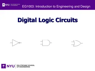
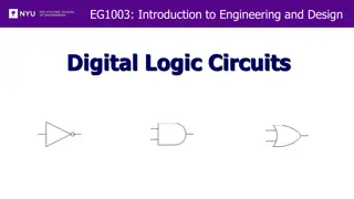
Types of Logic Gates There are seven different types of Gates. AND gate OR gate NOT gate NAND gate NOR gate Ex-OR gate Ex-NOR gate
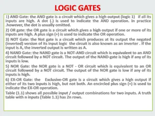
AND Gate The AND gate is an electronic circuit that gives a high output (1) only if all its inputs are high. A dot (.) is used to show the AND operation i.e. A.B. Bear in mind that this dot is sometimes omitted i.e. AB
NOT Gate The NOT gate is an electronic circuit that produces an inverted version of the input at its output. It is also known as an inverter. If the input variable is A, the inverted output is known as NOT A. This is also shown as A', or A with a bar over the top.
OR Gate The OR gate is an electronic circuit that gives a high output (1) if one or more of its inputs are high. A plus (+) is used to show the OR operation.
NAND gate This is a NOT-AND gate which is equal to an AND gate followed by a NOT gate. The outputs of all NAND gates are high if any of the inputs are low. The symbol is an AND gate with a small circle on the output. The small circle represents inversion.
NOR gate This is a NOT-OR gate which is equal to an OR gate followed by a NOT gate. The outputs of all NOR gates are low if any of the inputs are high. The symbol is an OR gate with a small circle on the output. The small circle represents inversion.
Exclusive-OR/ XOR GATE: The 'Exclusive-OR' gate is a circuit which will give a high output if one of its inputs is high but not both of them. The XOR operation is represented by an encircled plus sign.
EXCLUSIVE-NOR/Equivalence GATE: It will give a low output if one of its inputs is high but not both of them. The 'Exclusive-NOR' gate is a circuit that does the inverse operation to the XOR gate. The small circle represents inversion
EX-OR gateThe 'Exclusive-OR' gate is a circuit which will give a high output if either, but not both, of its two inputs are high. An encircled plus sign ( ) is used to show the EOR operation.