Major and Minor Losses in Pipes for Efficient Fluid Flow
Discover the concepts of major and minor losses in pipes, including their calculations and impact on energy considerations in pipe flow. Learn about the factors contributing to friction losses and the significance of fittings such as bends and area changes in optimizing fluid flow efficiency.
Download Presentation

Please find below an Image/Link to download the presentation.
The content on the website is provided AS IS for your information and personal use only. It may not be sold, licensed, or shared on other websites without obtaining consent from the author. If you encounter any issues during the download, it is possible that the publisher has removed the file from their server.
You are allowed to download the files provided on this website for personal or commercial use, subject to the condition that they are used lawfully. All files are the property of their respective owners.
The content on the website is provided AS IS for your information and personal use only. It may not be sold, licensed, or shared on other websites without obtaining consent from the author.
E N D
Presentation Transcript
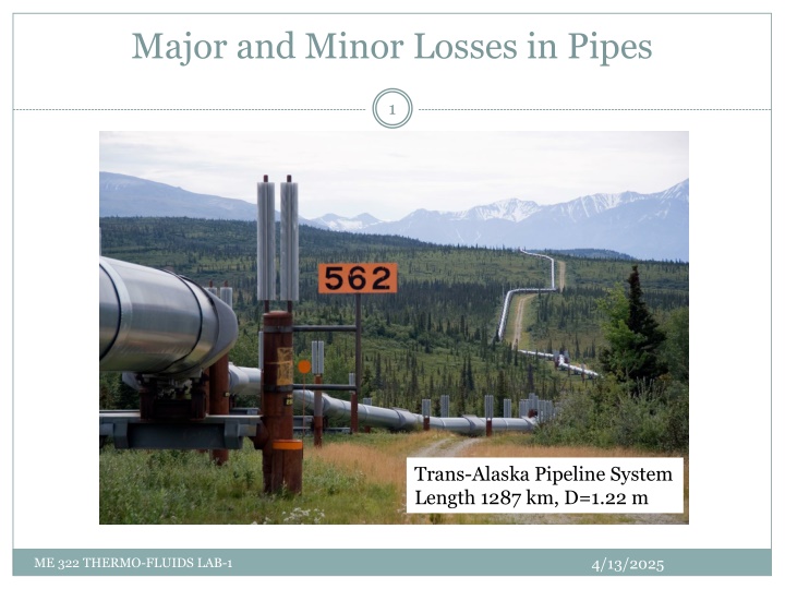
Major and Minor Losses in Pipes 1 Trans-Alaska Pipeline System Length 1287 km, D=1.22 m 4/13/2025 ME 322 THERMO-FLUIDS LAB-1
Major and Minor Losses in Pipes 2 Energy Considerations in Pipe Flow ?1 ?+?1 ?12 2 This equation enables us to calculate the losses occurring in a section of the pipe. The values of ? are usually close to 1. Each term in the equation has dimensions of ?2 ?, it would have dimensions of length ?. ?1 ??+?1 ?12 2? ?1+?1? ?12 2 ?2 ?+?2 ?22 + ??1 + ??2 = ?? 2 ?2 , so if we divide by ?2 ??+?2 ?22 = ?? + ?1 + ?2 = ??? 2? ? + ?1 ?2+?2? ?22 = ? ??= ?? ?2 + ???2 2 2 4/13/2025 ME 322 THERMO-FLUIDS LAB-1
Major and Minor Losses in Pipes 3 Energy Considerations in Pipe Flow ?1+?1? ?12 2 Major losses are due to friction between fluid and pipe, hence we can write the losses as, ?= ?? Where L and D are the pipe length and diameter, respectively. Minor losses are due to fittings and or area changes Inlets/Exits Enlargements and Contractions Pipe Bends Valves and fittings ?2 2= ??? We can define Le, equivalent length, for each type of fitting. + ?1 ?2+?2? ?22 = ? ??= ?? ?2 + ???2 2 2 ?2 2 ? ?2 2 ?= ? ? 4/13/2025 ME 322 THERMO-FLUIDS LAB-1
Major and Minor Losses in Pipes 4 Fittings: Area Change 4/13/2025 ME 322 THERMO-FLUIDS LAB-1
Major and Minor Losses in Pipes 5 Fittings: Bends 4/13/2025 ME 322 THERMO-FLUIDS LAB-1
Major and Minor Losses in Pipes 6 Fittings: Equivalent Length The equivalent length is calculated using the flow velocity and Reynolds number to get an estimate for f using Moody chart Using the estimated value of K we can estimate Le/D 4/13/2025 ME 322 THERMO-FLUIDS LAB-1

