Master-Slave JK Flip-Flop in Digital Electronics
Explore the concept of a Master-Slave JK flip-flop, its working principle, and applications in digital electronics. Learn about the block diagram, timing diagrams, and operational behavior of this fundamental circuit element.

Download Presentation

Please find below an Image/Link to download the presentation.
The content on the website is provided AS IS for your information and personal use only. It may not be sold, licensed, or shared on other websites without obtaining consent from the author. If you encounter any issues during the download, it is possible that the publisher has removed the file from their server.
You are allowed to download the files provided on this website for personal or commercial use, subject to the condition that they are used lawfully. All files are the property of their respective owners.
The content on the website is provided AS IS for your information and personal use only. It may not be sold, licensed, or shared on other websites without obtaining consent from the author.
E N D
Presentation Transcript
Digital Electronics Presented by Mrs. RautAarti P. Assistant Professor Department of Comp. Sci. & IT. Deogiri College, Aurangabad
Master Slave JK flip flop The Master-Slave Flip-Flop is basically a combination of two JK flip-flops connected together in a series configuration. Out of these, one acts as the master and the other as a slave . The output from the master flip flop is connected to the two inputs of the slave flip flop whose output is fed back to inputs of the master flip flop. In addition to these two flip-flops, the circuit also includes an inverter. The inverter is connected to clock pulse in such a way that the inverted clock pulse is given to the slave flip-flop. In other words if CP=0 for a master flip-flop, then CP=1 for a slave flip-flop and if CP=1 for master flip flop then it becomes 0 for slave flip flop.
Working of a master slave flip flop When the clock pulse goes to 1, the slave is isolated; J and K inputs may affect the state of the system. The slave flip-flop is isolated until the CP goes to 0. When the CP goes back to 0, information is passed from the master flip-flop to the slave and output is obtained. Firstly the master flip flop is positive level triggered and the slave flip flop is negative level triggered, so the master responds before the slave. If J=0 and K=1, the high Q output of the master goes to the K input of the slave and the clock forces the slave to reset, thus the slave copies the master. If J=1 and K=0, the high Q output of the master goes to the J input of the slave and the Negative transition of the clock sets the slave, copying the master. If J=1 and K=1, it toggles on the positive transition of the clock and thus the slave toggles on the negative transition of the clock. If J=0 and K=0, the flip flop is disabled and Q remains unchanged.
Conti When the Clock pulse is high the output of master is high and remains high till the clock is low because the state is stored. Now the output of master becomes low when the clock pulse becomes high again and remains low until the clock becomes high again. Thus toggling takes place for a clock cycle. When the clock pulse is high, the master is operational but not the slave thus the output of the slave remains low till the clock remains high. When the clock is low, the slave becomes operational and remains high until the clock again becomes low. Toggling takes place during the whole process since the output is changing once in a cycle. This makes the Master-Slave J-K flip flop a Synchronous device as it only passes data with the timing of the clock signal.
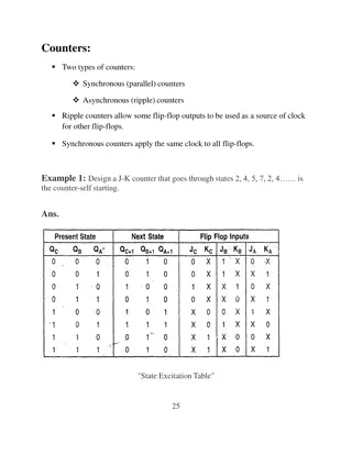
Counters A counter is basically used to count the number of clock pulses applied to a flip-flop. It can also be used for Frequency divider, time measurement, frequency measurement, distance measurement and also for generating square waveforms. In this, the flip-flops are asynchronous counters and are supplied with different clock signals, there may be a delay in producing output. Also, a few numbers of logic gates are needed to design asynchronous counters. So they are elementary in design and also are less expensive. Counter is a sequential circuit. A digital circuit which is used for a counting pulses is known counter. Counter is the widest application of flip-flops. It is a group of flip-flops with a clock signal applied. Counters are of two types. Asynchronous or ripple counters. Synchronous counters.
Asynchronous or ripple counters A n-bit ripple counter can count up to 2nstates. It is also known as MOD n counter. It is known as ripple counter because of the way the clock pulse ripples its way through the flip-flops. Some of the features of ripple counter are: It is an asynchronous counter. Different flip-flops are used with a different clock pulse. All the flip-flops are used in toggle mode. Only one flip-flop is applied with an external clock pulse and another flip-flop clock is obtained from the output of the previous flip-flop. The flip-flop applied with external clock pulse act as LSB (Least Significant Bit) in the counting sequence.
Conti The logic diagram of a 3-bit ripple up counter is shown in figure. The toggle (T) flip-flop are being used. But we can use the JK flip-flop also with J and K connected permanently to logic 1. External clock is applied to the clock input of flip-flop A and QAoutput is applied to the clock input of the next flip-flop i.e. FF-B.
Modulus Counter (MOD-N Counter) The 2-bit ripple counter is called as MOD-4 counter and 3-bit ripple counter is called as MOD-8 counter. So in general, an n-bit ripple counter is called as modulo-N counter. Where, MOD number = 2n. Type of modulus 2-bit up or down (MOD-4) 3-bit up or down (MOD-8) 4-bit up or down (MOD-16) Application of counters Frequency counters Digital clock Time measurement A to D converter Frequency divider circuits Digital triangular wave generator.
What is a Synchronous Counter? A synchronous counter, in contrast to an asynchronous counter, is one whose output bits change state simultaneously, with no ripple. The only way we can build such a counter circuit from J-K flip-flops is to connect all the clock inputs together, so that each and every flip-flop receives the exact same clock pulse at the exact same time


")