Microwave Instability in High-Energy Particle Accelerators
Observation of longitudinal microwave instability in CERN's SPS, impacting beam stability in proton machines and posing limitations for intensity increase projects like HL-LHC. Detailed study on uncontrolled emittance blow-up and impedance identification in multi-RF systems.

Download Presentation

Please find below an Image/Link to download the presentation.
The content on the website is provided AS IS for your information and personal use only. It may not be sold, licensed, or shared on other websites without obtaining consent from the author.If you encounter any issues during the download, it is possible that the publisher has removed the file from their server.
You are allowed to download the files provided on this website for personal or commercial use, subject to the condition that they are used lawfully. All files are the property of their respective owners.
The content on the website is provided AS IS for your information and personal use only. It may not be sold, licensed, or shared on other websites without obtaining consent from the author.
E N D
Presentation Transcript
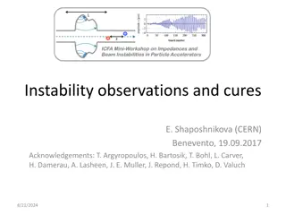
Longitudinal Microwave Instability in a Multi- RF System T. Argyropoulos Acknowledgements: H, Bartosik, T. Bohl, F. Caspers, H. Damerau, A. Lasheen, J. E. Muller , D. Quartullo, B. Salvant, E. Shaposhnikova H. Timk , J. E. Varela, C. Zannini LIU-SPS BD WG 06/11/2014
Outline Introduction Uncontrolled longitudinal emittance blow-up in the SPS Beam observations Impedance identification Longitudinal instability of a high frequency resonator Single RF system Double RF system Present situation in the CERN SPS Summary
Introduction Microwave instability observed in the proton machines as a fast increase of the bunch length (longitudinal emittance) Microwave ( w) instability observed in the CERN SPS in the past main source the resonant (Q~50) impedance of the pumping ports (~1000) shielding them improved the beam stability Today, SPS mainly used as the injector of the LHC Recently w instability was seen for a single proton bunch at high energies in the SPS one of the limitations for an intensity increase required by the HL-LHC project
Uncontrolled emittance blow-up (1/3) Measurements of high intensity single bunch at the SPS flat top Double RF systems (200 MHz + 800 MHz) in bunch shortening mode (BSM) with V800 = V200/10 Measurements in 2012 Emittance blow-up can not be explained by potential well distortion with the SPS impedance model (ImZ/n ~ 3.5 but ImZ/n >15 is needed) due to high frequency resonant impedance w instability blow-up during ramp
Uncontrolled emittance blow-up (2/3) Single bunch with high intensity in double RF system (V800 = V200/10) 200 MHz RF voltage calculated for constant bucket area 0.5 eVs larger filling factor during cycle more Landau damping Measurements in 2014 in Double RF BSM For ?? 0.26 eVs ?? 2.5x10¹¹ p Instability during ramp
Uncontrolled emittance blow-up (3/3) Lower threshold in a single RF system with same 200 MHz voltage program (bucket area = 0.5 eVs) Measurements in 2014 in Single RF For ?? 0.26 eVs ?? 1.7x10¹¹ p Instability during ramp
Impedance identification (1/2) Beam measurements at injection energy (26 GeV/c) with long bunches (?~25 ns) and RF off Example at Np = 1.0x10¹¹ p Small momentum spread more unstable and slow debunching Line density modulated at 200 MHz and a higher frequency (1.4 GHz) 200 MHz TWC Fourier Transform
Impedance identification (2/2) Impedance measurements and electromagnetic simulations for different devices/structures in the SPS ring: Vacuum flanges are the best candidate with strong peak at fr = 1.4 GHz with R/Q = 9 k (different types,~ 500) Group I Group II
w instability with a resonator Microwave instability threshold in a single RF system: broad-band impedance: ??? ? ??? ?? ??? ? ??? narrow band impedance: ??? ? ??? Particle simulations carried out to verify this analytical result using the code BLonD (longitudinal beam dynamics code developed at CERN) ????> ? % or ???> ??? ps = 0.3 eVs Nth =3.5E11 Q20 - Double RF - V200 = 7 MV Criterion for Instability threshold: = 0.5 eVs Nth =3.4E11 ???> ??? ????> ? %
Simulations single RF (1/2) Simulations at SPS flat top (450 GeV/c) with V200 = 2 MV Scanning ? but keeping ???/?constant Instability threshold from simulations in a single RF Same threshold for ? ?? narrow-band regime ???/? is important For ? < ?? broad-band regime ??? is important
Simulations single RF (2/2) Simulations at SPS flat top (450 GeV/c) with V200 = 2 MV Scanning ? but keeping ???/?constant Instability threshold from simulations in a single RF ??? < ?: ? ?? ??? < ?/?? narrow-band regime ? < ?? ??? ?/?? approaching the broad-band regime
Simulations double RF (1/2) Second harmonic RF system: h2/h1 = 2 and V1/V2=2 Simulations at SPS flat top (450 GeV/c) with V200 = 2 MV Similar dependence with ???/? ? = 10 ? = 250 Double RF in BSM has the highest threshold and double RF in BLM the lowest Dependence on the ??/?
Simulations double RF (2/2) Fourth harmonic RF system: h2/h1 = 4 (SPS today) Simulations at SPS flat top (450 GeV/c) with V200 = 2 MV ? = 250 After a certain ?? single RF is better for stability Can be correlated with the synchrotron frequency distribution inside the bunch (?)
SPS longitudinal impedance model Includes: RF cavities, resistive wall, injection and extraction kickers, Beam Position Monitors (BPMs), vacuum flanges etc. The SPS longitudinal impedance model 200 MHz TWC Vacuum flanges Jose E. Varela et al.
Simulations vs measurements Macroparticle simulations at the SPS flat top (450 GeV/c) using the full SPS impedance model ? ?0)2 Distribution function: ? ? = (1 form measurements Double RF V200 = 2 MV V800 = 0.2 MV N=1.47x10¹¹ p Discrepancy due to transfer functions
Simulations vs measurements single bunch Double RF V200 = 2 MV V800 = 0.2 MV N=1.47x10¹¹ p Good agreement between measurements and simulations From measurements in 2014: ??? 2.5x10¹¹ p (more points are needed) From particle simulations with ?? 0.35 eVs (maximum single particle trajectory): ???= 2.5x10¹¹ p Measurement in 2012 correspond to higher initial ?? 0.45 eVs (from simulations) but points at lower intensity are missing In simulation: ???= 2.0x10¹¹ p
Simulations vs measurements single bunch Increasing the RF voltage in both RF systems increase the instability threshold larger ??/? larger w type of instability Double RF - ?? (??) Probably due to the synchrotron frequency distribution inside the bunch Complicated shape: ?? ? = 0 in both but much more spread in the case of ??= 0.3 eVs
Simulations vs measurements multi-bunch Simulations for 6 bunches (25 ns spacing) at SPS flat top Intensity threshold as a function of bunch length for 1 & 6 bunches Qualitative agreement of simulations with measurements: Double RF V200 = 7 MV V800 = 0.7 MV Nth of 6 bunches is ~ twice lower than of single bunch (limitation for the HL- LHC parameters ~ 2.5x10¹¹ p/b) Only a few bunches are coupled, no coupled bunch modes indeed in measurements 25 ns and 50 ns spaced bunches are coupled, but batches spaced by 225 ns are decoupled Nth increases with emittance Preliminary results show that Nth increases by a factor of 2 without the impedance of vacuum flanges (single and multi bunch) impedance reduction under discussion
Summary Signs of w instability are observed in the SPS uncontrolled emittance blow- up Beam measurements identified the vacuum flanges as the main impedance source (strong resonant peak at 1.4 GHz and many more resonances with high Q values) w instability threshold for this type of resonators scale with R/Q (as expected from theory in single RF) Double RF vs single RF h2/h1 = 2: higher Nth in BSM and lower in BLM (as expected from p/p) h2/h1 = 4: lower Nth in BSM above a certain emittance Simulations with the current SPS longitudinal impedance model verify the uncontrolled blow-up good agreement with the measurements Nth increases by a factor of 2 without the impedance of vacuum flanges (single and multi bunch) impedance reduction under discussion at CERN


")
")
")
")
")

")
")
")
")