Millimeter Wave Communication Control PHY Design Overview
Explore the design requirements and considerations for Control PHY in 40-50GHz millimeter wave communication systems. The proposal focuses on implementing a Control PHY with low complexity and high performance, essential for supporting beamforming in challenging SNR environments. Details include beamforming gain calculations, modulation techniques, and spreading strategies using Barker Sequences for optimal SNR enhancement.

Download Presentation

Please find below an Image/Link to download the presentation.
The content on the website is provided AS IS for your information and personal use only. It may not be sold, licensed, or shared on other websites without obtaining consent from the author. If you encounter any issues during the download, it is possible that the publisher has removed the file from their server.
You are allowed to download the files provided on this website for personal or commercial use, subject to the condition that they are used lawfully. All files are the property of their respective owners.
The content on the website is provided AS IS for your information and personal use only. It may not be sold, licensed, or shared on other websites without obtaining consent from the author.
E N D
Presentation Transcript
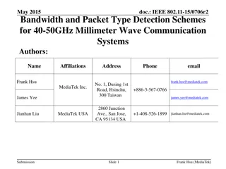
May 2015 doc.: IEEE 802.11-15/0705r1 Control PHY Design for 40-50GHz Millimeter Wave Communication Systems Authors: Name Affiliations Address Phone email 2860 Junction Ave., San Jose, CA 95134 USA Jianhan Liu MediaTek USA +1-408-526-1899 jianhan.liu@mediatek.com Frank Hsu frank.hsu@mediatek.com No. 1, Dusing 1st Road, Hsinchu, 300 Taiwan MediaTek Inc. +886-3-567-0766 James Yee james.yee@mediatek.com Submission Slide 1 Jianhan Liu, et. al. (MediaTek)
May 2015 doc.: IEEE 802.11-15/0705r1 Introduction Link budget analysis shows that beamforming is needed to support 10m NLOS[1] Discovery and beamforming training needs control PHY that works in low SNR environments This proposal designs a Control PHY with low implementation complexity and good performance Submission Slide 2 Jianhan Liu, et. al. (MediaTek)
May 2015 doc.: IEEE 802.11-15/0705r1 Design Requirements on Control PHY[1] One side beamforming gain can be provided by sector level sweep Gain is about 10*log10(N), N it the number of antenna, for example, using 8 antennas can get 6-9 dB Note that receive antenna gain does not count Tx power increase. Assume 8dB Gain is provided by one side beamforming, than extra gain 8dB is needed for BPSK and LDPC rate code. We need a low rate PHY that can operate at SNR: -8+1.0=-7 dB. Submission Slide 3 Jianhan Liu, et. al. (MediaTek)
May 2015 doc.: IEEE 802.11-15/0705r1 Control PHY Design Control PHY Preamble still uses ZCZ sequences Easier for implementation since common preamble sequences for SC PHY and OFDM PHY [2] Control PHY is only transmitted in 540MHz channel To get extra range and reduce the complexity Control PHY Header and Data portion Modulation: BPSK with LDPC encoded Single Carrier (SC) with Spreading Spreading factor is changeable for flexible designs and different spectrum efficiency. Submission Slide 4 Jianhan Liu, et. al. (MediaTek)
May 2015 doc.: IEEE 802.11-15/0705r1 Spreading with Barker Sequences Spreading using Barker Sequences Barker sequence is a finite sequence of N values of +1 and 1 with ideal correlation property The chosen spreading sequences are in read and filled with blue color. Barker Sequence has the lowest sidelobe level ratio among all binary sequences Spreading with factor 13 provides 11dB SNR enhancement Length Codes Sidelobe level ratio SNR Gain 2 +1 +1 3dB +1 1 6 dB 3 4.7dB +1 +1 1 9.5 dB 4 6dB +1 +1 1 +1 +1 +1 +1 1 12 dB 5 7dB +1 +1 +1 1 +1 14 dB 7 8.4dB +1 +1 +1 1 1 +1 1 16.9 dB 11 10.4dB +1 +1 +1 1 1 1 +1 1 1 +1 1 20.8 dB 13 11.1dB +1 +1 +1 +1 +1 1 1 +1 +1 1 +1 1 +1 22.3 dB Submission Slide 5 Jianhan Liu, et. al. (MediaTek)
May 2015 doc.: IEEE 802.11-15/0705r1 Signaling on spreading factor Spreading factor signaling information can be conveyed using a field control PHY header PHY header is spread with barker sequence 13 and with fixed encoding schemes. Field name Number of Bits Starting Bit Description Set to 0 (differential detector initialization). Reserved 1 0 Bits of the initial scrambler state Scrambler Initialization 4 1 Number of data octets in the PSDU. Range 14-1023. Length 10 5 TRN packet type Packet Type Training Length 1 15 Length of the training field. 5 16 Turnaround Set to 1 if the STA is transmitting a packet during an SP or TXOP. Set to 0: spreading by 13 Set to 1: spreading by 7 Set to 2: spreading by 4 Set to 3: no spreading Header Check sequence. 1 21 Spreading Factor 2 22 HCS 16 24 Submission Slide 6 Jianhan Liu, et. al. (MediaTek)
May 2015 doc.: IEEE 802.11-15/0705r1 Simulation Settings LDPC code rate BPSK modulation Spreading factor 4, 5, 7, 11, 13 Packet size 42 bytes (336 bits) Real Channel Estimation based on Channel Estimation Sequences using ZCZ 256 sequences AWGN, Exp 4ns, Exp 10 ns, Exp 20 ns channels Submission Slide 7 Jianhan Liu, et. al. (MediaTek)
May 2015 doc.: IEEE 802.11-15/0705r1 PER in AWGN Channels 0 10 SF13 AWGN SF11 AWGN SF7 AWGN SF5 AWGN SF4 AWGN SF SNR (dB) @10-1 PER -11.2 -10.6 -9.1 -7.9 -7.0 -1 10 PER BLOCK ERROR RATE 13 11 7 5 4 -2 10 -3 10 -12 -11 -10 -9 -8 -7 -6 -5 SNR (dB) With Spreading 13, system can work at SNR less than -11dB, which is good enough for an AP with 4 TX antennas. Submission Slide 8 Jianhan Liu, et. al. (MediaTek)
May 2015 doc.: IEEE 802.11-15/0705r1 BLER in Exp 4ns Channels 0 10 SF13 Exp 4ns SF11 Exp 4ns SF7 Exp 4ns SF5 Exp 4ns SF4 Exp 4ns SF SNR (dB) @10-1 PER -10.6 -9.9 -8.2 -6.7 -5.2 -1 10 PER BLOCK ERROR RATE 13 11 7 5 4 -2 10 -3 10 -12 -10 -8 -6 -4 -2 0 SNR (dB) Submission Slide 9 Jianhan Liu, et. al. (MediaTek)
May 2015 doc.: IEEE 802.11-15/0705r1 BLER in Exp 10ns Channels 0 10 SF13 Exp 10ns SF11 Exp 10ns SF7 Exp 10ns SF5 Exp 10ns SF4 Exp 10ns -1 10 PER BLOCK ERROR RATE -2 10 SF SNR (dB) @10-1 PER -9.7 -9.2 -7.3 -5.3 -3.2 13 11 7 5 4 -3 10 -12 -10 -8 -6 -4 -2 0 SNR (dB) Submission Slide 10 Jianhan Liu, et. al. (MediaTek)
May 2015 doc.: IEEE 802.11-15/0705r1 BLER in Exp 20ns Channels 0 10 SF13 Exp 20ns SF11 Exp 20ns SF7 Exp 20ns SF5 Exp 20ns SF4 Exp 20ns -1 10 PER BLOCK ERROR RATE -2 10 SF SNR (dB) @10-1 PER -8.1 -7.5 -5.6 -3.1 -0.2 13 11 7 5 4 -3 10 -12 -10 -8 -6 -4 -2 0 2 4 SNR (dB) Submission Slide 11 Jianhan Liu, et. al. (MediaTek)
May 2015 doc.: IEEE 802.11-15/0705r1 Performance Summary SNR @ 10-1 PER SF 13 11 7 5 4 AWGN -11.2 -10.6 -9.1 -7.9 -7.0 Exp 4ns -10.6 -9.9 -8.2 -6.7 -5.2 Exp 10 ns -9.7 -9.2 -7.3 -5.3 -3.2 Exp 20ns -8.1 -7.5 -5.6 -3.1 -0.2 Submission Slide 12 Jianhan Liu, et. al. (MediaTek)
May 2015 doc.: IEEE 802.11-15/0705r1 Summary Link Budget analysis shows that a control PHY that works in low SNR regime is required. We propose a control PHY design with low implementation cost and good PER performance. Submission Slide 13 Jianhan Liu, et. al. (MediaTek)
May 2015 doc.: IEEE 802.11-15/0705r1 References [1] WPAN-PG4-T-14-036-00 Mediatek Introduction to Beamforming Protocols for 40-50GHz [2] Complete-specification-proposal-IEEE-802.11aj(45GHz)_v0.1.1 Submission Slide 14 Jianhan Liu, et. al. (MediaTek)
May 2015 doc.: IEEE 802.11-15/0705r1 BACKUP Submission Slide 15 Jianhan Liu, et. al. (MediaTek)
May 2015 doc.: IEEE 802.11-15/0705r1 Link Budget for NLOS case Extra gain needed SNR requirement is 1.0 dB for BPSK, rate code Extra Gain Needed: 20*log10(d)-(Rx_SNR-required_SNR)=16dB Tx power (dBm) Tx Antenna Gain Center Frequency (GHz) Propogation Loss at 1m (dB) Shawdowing+link margin RX antenna Gain Receiver Signal Strength 10 0 45 65.56425 10 0 -65.5643 Rx Noise Figure (dB) Immeplentaion loss (dB) BW (GHz) Noise Floor RX SNR (dB) 10 2 1 -84 6.43575 SNR BPSK, LDPC 1/2 Distance (m) extra gain needed for 10m NLOS (dB) 1.0 1.573213 16.06425 Submission Slide 16 Jianhan Liu, et. al. (MediaTek)