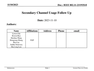
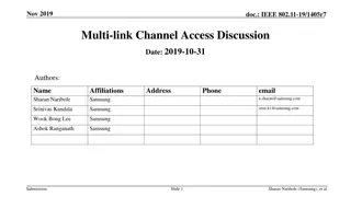
Multi-link Channel Access in IEEE 802.11-19/1836r2
This document discusses multi-link channel access in IEEE 802.11-19/1836r2, focusing on asynchronous and synchronous operations, multi-link TXOP aggregation, and constraints related to non-AP Station (STA) operations. It covers topics such as simultaneous transmit-receive, transmit-transmit, and receive-receive scenarios, as well as considerations for handling simultaneous operations on different channels and antenna limitations.

Download Presentation

Please find below an Image/Link to download the presentation.
The content on the website is provided AS IS for your information and personal use only. It may not be sold, licensed, or shared on other websites without obtaining consent from the author.If you encounter any issues during the download, it is possible that the publisher has removed the file from their server.
You are allowed to download the files provided on this website for personal or commercial use, subject to the condition that they are used lawfully. All files are the property of their respective owners.
The content on the website is provided AS IS for your information and personal use only. It may not be sold, licensed, or shared on other websites without obtaining consent from the author.
E N D
Presentation Transcript
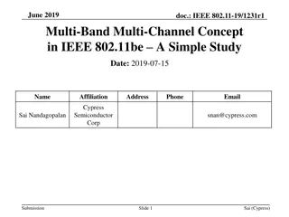
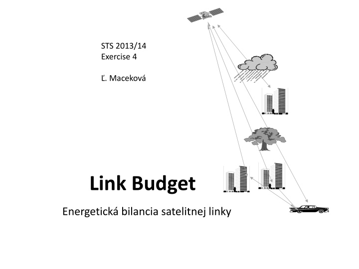
STS 2013/14 Exercise 4 . Macekov Link Budget Energetick bilancia satelitnej linky
Satellite LNA HPA G/T EIRP Frequency convertor DIP DIP Antenna HPA LNA Transponder Attenuation by precipitation Attenuation by precipitation Blocking Shielding ! Antenna Multipath propagation and fading (because of reflections) MOD U/C HPA Acoustic data DIP Antenna, G/T, EIRP, C/No DEM D/C LNA Propagation path Propagation path Satellite Terrestrial exchange Mobile terrestrial station Fig. Illustration of several satellite link aspects [2]
Problems: - noise - gains and losses (also gains of antennas) - blocking - attenuation by surrounding environment (shielding by vegetation, rain - in the case of Ka-band and mm-waves) -multipath broadcasting (multiple reflections) multipath fading -reflection from sea level in the case of maritime communications But, at first, we must familiarize with: decibel measure of power, gain, attenuation, etc. noise power, SNR, noise temperature 3
Antenna gain in dependence on generalized aperture and referenced to gain of isotropic radiator : Gain ofparabolic antenna in dependence on both dish diameter an efficiency: 4 = 2 A [-] G 2 D a = [-] G max A ... effective radiated surface of antenna depends on diraction of setting of antenna = Aef[m2] A ... aperture (physical surface, passed by e-m radiation) [m2] GdBi = 10 log G [dBi] D ... diameter of dish (or of reflector, or of array of radiating elements, i.e. of aperture) [m] ... efficiency of aperture (0,35- 0,75) [-] Example: =55%, f=11GHz, D=1m. G=? ... wavelength [m] Results: about 7299 and 38dBi - actual gain is always < than value declared by producer (connection, direction and other unfavourable conditions) Example: Calculate of frequency channel at 900 MHz.
Decibels device or signal path P1 P2 G (L) If P2> P1 P P 2 P = 10 log dB GdB 2 P 1 Gain 1 1 Definition of dBm and dBW - if we transform: [W alebo mW] P[dBm]=10logP[mW] 1 / P mW > 0 dB = 2 10 log dB GdB 1 / P mW P[dBW]=10logP[W] 1 and by definition of dBm: Then similarly: attenuation, diminution, Loss = LdB = 10log(P2/1mW) 10 log( P1 /1mW) P 1 P 10 log dB G[dB]= P 2 [dBm] P 1 [dBm] 5 2 P1> P2; L > 0 dB
Examples ... 1 W ? dBW 1mW ? dBW 1mW ? dBm 10 mW ? dBm 35 mW ? dBm P1= 1mW, P2= 10 W, A = ? (A Attenuation) P = 35 dBm ? mW P = - 15 dBW ? W 6
Other parameters of satellite receiving
Noise ( um)
Noise, Signal-to-Noise Ratio SNR (S/N in [-]) and Signal-to- Noise Ratio in [dB] , Noise Figure F (or NF), noise voltage, noise power, Power Spectral Density of noise (PSDN), ... Effective noise voltage (by Nyquist [2]) 4kTRB Un= k Boltzmann konstant = 1,38. 10-23Ws-1K-1 T absolut. temperature [K] [V] R equiv. resistivity [ ] B frequency bandwidth [Hz] (thermal noise/white noise/Gauss additive noise) Signal-to-Noise Ratio in non-units [-] and in [dB] S/N ... ratio [W,W; result is without units] SNRdB= 10 log (S/N) [dB] = SdBm NdBm (S/N)in, (S/N)out, SNRin, SNRout [dB] S ... signal power N ... noise power ( um=noise) SNR ... signal-to-noise ratio
Power of noise (if matched connecting : Rsource=RLoad =R) 2 n U = = [W] P or N kTB n 4 R P density of energy N0 power spectral density of noise (power over unit of freq. spectrum, i.e. over 1 Hz): = n= N kT [W/Hz] 0 B ...symbolic notation for dB-calculi k = ( ) k log ( 38 . 1 log + N T if in [dB], so as follows: [dBW/Hz] 0 ( ) T ) ( ) T = = + 10 10 10 10 x log ( ) T 23+ 10 log = 228 + 6 . 10 log [dBW/Hz] Example: Evaluate density of noise energy of resistor at temperature 27 C Result: -203,8 dBW/Hz
Noise is property of every substance each el. amplifier, beyond amplifying of entering signal and noise, adds its own noise, as well. important parameter of active el. equipments (antennas, amplifiers, : Noise Figure (F) of device with gain G Sin,Nin, SNRin Sout,Nout, SNRout G...Gain F Sout = G . Sin Nout=G.Nin+Nown Noise figure NF, alebo len F umov slo akt vneho zariadenia (zosil ova a, ant ny at .) We know: S/N ... ratio [-] S in SNRdB= 10 log (S/N) [dB] (S/N)in, (S/N)out, SNRin, SNRout N T = = = + ... 1 in e F [without units] S T out 0 N where: out Te...equivalent noise temperature of el. device at the input Te ( ) 1 = And then in dB: T F 0 F = 10 log F = SNRin[dB] SNRout[dB] [dB] T0 ...operational (circumstances) physical temperature
Example 1: Evaluate the noise figure of amplifier at circumstances temperature T0= 300 K and at Tin = 400 K. Result: 3,7 dB Example 2: Calculate the equivalent input noise temperature of amplifier, if we know the circumstances temperature To= 290 K, and noise figure NF= 4 dB. Result: Te = 438,8 K
Noise Figure (FL) of device with insert loss L (attenuation) feed lines, cables, connectors, etc. Sin,Nin, SNRin FL input noise Sout,Nout, SNRout L ... Loss L > 1 Sout = Sin/L; Sout<Sin output noise noise figure FL umov slo zariadenia: Then input noise temperature: = T Te S S in in ) 1 ( L N kT B T = = = + = 0 1 in e F L 0 L S S T out in 0 And output noise temperature.: N L out 1 [without units] ( ) + 1 L kT B kT B 0 e = L 1 ( 0 T ) Tout Te...equivalent noise temperature at the input T0 ...operational (circumstances) temperature Tout ... Output noise temperature Then in dB: FL[dB] = 10 log FL [dB]
Example - both input and output noise temperatures of loss device: Circuit has loss 2,5 dB, operational temperature is 400 K. Evaluate equivalent noise temperature at both his input and output ports. Results: Te = 311,3 K, Tout=175,1 K Outcome: Circuit with loss decrements equivalent noise temperature suppresses noise!
Ga, Ta P1 G1 L1 L2 G2 Overall equivalent noise temperature of the complete cascade (converted into the point P1; not yet with antenna): T G T + stages (for examples antenna feed L1and input amplifier G1) !! (all G are >> 1) . . G L T L T = + + + + + 2 2 3 2 2 ... G L L T T T e L G . G G 1 1 1 1 1 2 T It depends almost on noise properties of first 1 1 L G That is, why requirement of LNA Low Noise Amplifier of receiver is important and crucial (our aim is: as best / as high SNR as possible !!). or LNC Low Noise Convertor
... with considering of antenna: Total noise temperature of system Tsat the input of receiver with antenna: T T = + + = 1 1 1 . 1 T + + 1 a a T T T T (*) 0 s L G R L L L f f or : T=Ta.a + (1-a)T0+(F-1)T0 where: TR ... noise temperature of the first amplifier stage of receiver (Low Noise Amplifier - LNA); TR = (F-1).T0 Lf ... loss of feed line (between antenna and LNA); LF=1/a ... about 1/ 0,95 Ta... noise temperature at output of antenna (about 80 K to 100K in L-band)
Gain of antenna and EIRP (Effective Isotropic Radiated Power) (We know, what are: isotropic antenna, directional antenna, beam width- at -3dB level of maximal power of signal) = its radiation effectivity in comparison with reference antenna, e.g. isotropic one (that means: the gain is the result of the ratio of 2 power densities!) : Gain of directional antenna Ga Ga = / i ... note.: G of isotrop. antenna is 1 (i.e. 0 dBi) Ga [dBi]= 10 log ( / i) ... [dBi] i = Pt / 4 R2 ... i ... density of radiated power of isotropic antenna(or PFD- Power Flux Density) [W/m2] Pt... radiated power [W] R .... distance between transmitting and receiving antennas [m] Note: PFD on the Earth surface (of the signal from satellite transmitter) falls with horizontal distance from nadir (nadir or boresight zamierenie - the point under the satellite; it relates with directional characteristic of antenna ...)
EIRP ... Equivalent Isotropic Radiated Power of satellite transmitter EIRP = Pt .Gt [-] or, in dB: [W; W, -] EIRP= Pt . Gt = Pt . ( t/ i) = ... = t. 4 R2 EIRP[dBW]= 10 log Pt [W]+ Gt [dBi] Pt radiated power (of transmitter) [W] Gt ... gain of transmitting antenna (on the sat.) Example: If EIRP of transmitter in GEO system is 48 dBW, calculate the maximal PFD on the Earth. result: -114 dBW/m2
The next parameters of system: G/T - Figure of merit (Syst mov zisk) - the ratio of the gain and noise temperature of equipment - important parameter higher the better - G/T of antennas mostly contains also noise temperature of convertor Example: Evaluate figure of merit of antenna with LNC-convertor. Noise figure of LNC is F=1,3, gain of antenna at mean frequency 12,1GHz is 34,75 dBi, its noise temperature is 31,68K, loss between radiator and convertor is about a=0,95, loss because of inaccurate bearing and polarization setting is about b=0,9. Consider reference operational temperature T0=290K. Solution: We use equation (*) for equivalent noise temperature of system of antenna with convertor: T=Ta.a + (1-a)T0+(F-1)T0; and for operational gain of antenna Gp=a.b.G[-]. then Gp/T= Result: 17,7 K-1... 12,48 dB/K
alie parametre systmu: Quality of receiving signal - Signal-to-Noise Ratio in Satellite Communication C/N Kvalita pr jmu (C-Carrier-nosn ,t.j. nosn frekvencia sign lu, N-Noise- um) - je to vlastne pomer sign lu a umu na vstupe pozemn ho prij ma a i e to, o sme predt m nazvali SNR . pozri alej C ( ) = / 10 log C N C/ [-]= Pt [W]. Gt.Gr..b / (k.T.B) [ ] dB N Pt...vyslan v kon, Gt,Gr...zisk vysielacej, resp. prij. ant ny, b- tlm vo .priestoru medzi ant nami in dB: C/ [dB]= Pt [dBW]+Gt[d ]+Gr[dB]+b[dB]-10logk-10logT-10logB 1 EIRP G When noise power density is C/N0is considered, we can write: ( ) = / C N R 0 [ ] dB L T k p S
b...tlm vonho priestoru od vysielacej antny ku prijmacej: 2 = [-; m, m] b ...vln.d ka 4 R R...vzdialenos (napr. 36.106 m pre GEO) Pr klad: Vypo ta tlm pre syst m GEO pri frekvencii 11 GHz. V sledok: -206dB
Now, link energy budget: v etky faktory sa zapo taj ako pr rastky (+) alebo m nusy (-) v [dB] (vi obr. na 2. slide) EIRP Tx Transmission: + power of HPA - transmission loss (cables and connectors) + Gain of antenna - loss of bearing of Tx antenna - Loss in the free space - Athmospheric loss (gases, clouds, precipitations) - loss of bearing of Tx antenna Receiving + gain of antenna - Receiving losses (cables and connectors) + noise temperature Pr Rx source [1]
Signal-to-Noise Ratio (C/N0) in total satellite link (up and down together)
In communications up- and down the total Signal-to-Noise Ratio C C = + + ( ) ( ) N N N I 0 0 0 0 U D T T ...total U ...uplink D ...downlink I0 ...intereference noise 1 = (***) 1 C 1 C 1 C + + ( ) ( ) ( ) N N I 0 0 0 U D Quality of receiving depends on the worste quality in some partial section of link (the principle of the weakest article of the chain )
[3] Example of calculation: Communication from Earth station to aeroplane station through satellite in the system ETS-V. (the older experimental system for communication ground-aircraft via satellite) Notes: GES ... gate Earth station, AES ... aircraft Earth station. From GES to satellite (uplink): GES EIRP .....................................................60,7 dBW propagation loss.........................................199,4 dB (d = 37270 km, f = 6GHz) satellite antenna gain..................................21,7 dBi feeder loss............................................3,0 dB uplink total C = 60,7-199,4+21,7-3,0= -120,0 dBW N0= 10log(kTB) = -228,6 + 10log300 + 10log1Hz= -203,8 dBHz (nie je zmienka o .p sma, tak e uva ujeme kvalitu na 1 Hz) s (C/N0)U= -120 + 203,8 = 83, 8 dBHz Zo satelitu na lietadlo (downlink): sat. EIRP .........................................30,5 dBW propagation loss...... 188,5 dB (d = 41097 km, f = 1,5 GHz) AES antenna gain................................21,7 dBi antenna tracking error ..............3,0 dB feeder loss...............................3,0 dB downlink total C = 60,7-199,4+21,7-3,0= -120,0 dBW N0=10log(kTB)= -228,6+10log300= -203,8 dBHz (C/N0)D= -147,5 + 203,8 = 56,3 dBHz continue
Calculation by (***) : 1 1 C = = = 425822 1 . 8 1 . 5 N + 0 T 38 63 1 C 1 C 10 10 + U D ( ) ( ) N N 0 0 U D C = = 10 log 425822 56 3 . N 0 T The result confirms, that total quality of communication channel equals to the worst one from partial links.
Zdroje: [1] J. Montana: Introduction to Satellite Communications, George Mason Univ. 2003 [2] Mobiln satelitn komunik cie [3] S. Ohmori, H. Wakana, S. Kawase : Mobile satellite communications, Artech House, 1998.


 and Signal-to-")
")


 of device with insert loss L")


 in total")


 :")