Multicore Navigator for Efficient Data Processing
Learn about the advantages and architecture of Multicore Navigator, including its functional role, configuration parameters, and key components like descriptors and queues. Discover how Multicore Navigator minimizes core intervention and optimizes data movement in a standard KeyStone architecture.

Download Presentation

Please find below an Image/Link to download the presentation.
The content on the website is provided AS IS for your information and personal use only. It may not be sold, licensed, or shared on other websites without obtaining consent from the author. If you encounter any issues during the download, it is possible that the publisher has removed the file from their server.
You are allowed to download the files provided on this website for personal or commercial use, subject to the condition that they are used lawfully. All files are the property of their respective owners.
The content on the website is provided AS IS for your information and personal use only. It may not be sold, licensed, or shared on other websites without obtaining consent from the author.
E N D
Presentation Transcript
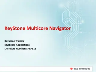
KeyStone Multicore Navigator KeyStone Training Multicore Applications Literature Number: SPRP812
Objectives The purpose of this lesson is to enable you to do the following: Explain the advantages of using Multicore Navigator. Explain the functional role of descriptors and queues in the Multicore Navigator. Describe Multicore Navigator architecture and explain the purpose of the Queue Manager Subsystem and Packet DMA. Identify Multicore Navigator parameters that are configured during initialization and how they impact run-time operations. Identify the TI software resources that assist with configuration and usage of the Multicore Navigator. Apply your knowledge of Multicore Navigator architecture, functions, and configuration to make decisions in your application development. 2
Agenda Part 1: Understanding Multicore Navigator: Functional Overview and Use Cases System Architecture Implementation Examples Part 2: Using Multicore Navigator: Configuration LLD Support Project Examples 3
Understanding Multicore Navigator: Functional Overview and Use Cases KeyStone Multicore Navigator
Motivation Multicore Navigator is designed to enable the following: Efficient transport of data and signaling Offload non-critical processing from the cores, including: Routine data into the device and out of the device Inter-core communication Signaling Data movement loose link Minimize core intervention: Fire and forget Load balancing through a centralized logic control that monitors execution status in all cores A standard KeyStone architecture 5
Basic Elements Data and/or signaling is carried in software structures called Descriptors: Contain information and data Allocated in device memory Descriptors are pushed and popped to and from hardware Queues: Cores retrieve descriptors out of queues to load data Cores get data from descriptors When descriptors are created, they are pushed into special storage queues called Free Descriptor Queues (FDQ). 6
Typical Use Cases (1) Send routing data out via a peripheral: 1. Core 1 generates data to be sent out. 2. Core 1 gets an unused descriptor from a FDQ. 3. Core 1 connects data to the descriptor. 4. If the destination is not yet defined, Core 1 defines the destination and adds more information to the descriptor (as needed). 5. Core 1 pushes the descriptor to a (dedicated TX) queue. At this point, Core 1 is done. 6. Multicore Navigator hardware sends the data via the peripheral to the destination. 7. The used descriptor is recycled back to the FDQ. Multicore Navigator CPU Peripheral Generate data POP descriptor Connect data Push to TX queue Data goes out 7
Typical Use Cases (2) Getting data from a peripheral to a pre-defined core destination: 1. Peripheral receives external data with protocol-specific destination routing information. 2. Multicore Navigator hardware inside the peripheral gets a descriptor from FDQ and loads data to the descriptor. 3. Based on Receive Flow rules and protocol routing information, Multicore Navigator hardware pushes the descriptor into a queue associated with the destination (Core 1) 4. At this point, the destination (Core 1) pops the descriptor from the queue, reads the data, and recycles the descriptor back to the FDQ. Multicore Navigator CPU Peripheral Receive data from outside POP descriptor Load descriptor with data and information Push descriptor Push to RX queue CPU pops descriptor, processes it and releases it to FDQ 8
Typical Use Cases (3) Multicore Navigator CPU 1 CPU 2 Send data from one core to another core. 1. Core 1 generates data to be sent out. 2. Core 1 gets an unused descriptor from a FDQ. 3. Core 1 connects data to the descriptor. 4. If the destination is not yet defined, Core 1 defines the destination and adds more information to the descriptor, as needed. 5. Core 1 pushes the descriptor to a queue. At this point, Core 1 is done. 6. The hardware sends the data to a queue that is associated with Core 2. 7. At this point, Core 2 pops the descriptor from the queue, reads the data, and recycles the descriptor to the FDQ. Generate data POP descriptor Connect data Push to TX queue Descriptor goes to RX queue CPU 2 pops descriptor, processes it, and releases it to FDQ 9
Understanding Multicore Navigator: System Architecture KeyStone Multicore Navigator
KeyStone Navigator Components The Queue Manager Subsystem (QMSS) is a centralized hardware unit that monitors core activity and manages the queues. Multiple Packet DMA (PKTDMA) engines use descriptors between transmit and receive queues packets that are dedicated to routing peripherals or to the Multicore Navigator infrastructure. NOTE: PKTDMA was previously called CPPI (Communication Peripheral Port Interface) Application-Specific Coprocessors Memory Subsystem MSM SRAM DDR3 EMIF MSMC C66x CorePac L1D L1P Cache/RAM L2 Memory Cache/RAM Cache/RAM 1 to 8 Cores @ up to 1.25 GHz Miscellaneous TeraNet HyperLink Multicore Navigator Queue Manager Packet DMA External Interfaces Network Coprocessor
QMSS Architecture (KeyStone 1) Major HW components of the QMSS: Queue Manager and 8192 queue headers Two PDSPs (Packed Data Structure Processors): Descriptor Accumulation / Queue Monitoring Load Balancing and Traffic Shaping TI provides firmware code to the APDSP; The user does not develop any firmware code. Interrupt Distributor (INTD) module Two timers Internal RAM: A hardware link list for descriptor indices (16K entries) Infrastructure PKTDMA supports internal traffic (core to core) TeraNet QMSS Timer Timer PKTDMA (internal) APDSP (Accum) APDSP (Monitor) Interrupt Distributor Queue Interrupts que pend Queue Manager Config RAM queue pend Register I/F Link RAM (internal) 12
KeyStone II QMSS Architecture Queue Manager Sub System (Keystone 2) QM 1 (queues 0..8191) QM 2 (queues 8192..16383) Link RAM (32K entries) Link ram cfg Desc mem cfg Link ram cfg Desc mem cfg que_pend que_pend que_pend PktDMA 2 PktDMA 1 PDSP 1 PDSP 3 PDSP 5 PDSP 7 PDSP 2 PDSP 4 PDSP 6 PDSP 8 Timer Timer Timer Timer Timer Timer Timer Timer INTD 1 INTD 2 INTD 1 INTD 2 Que interrupts 13
Keystone I Queue Mapping Queue Range Count Hardware Type Purpose 0 to 511 512 pdsp/firmware Low Priority Accumulation queues 512 to 639 128 queue pend AIF2 Tx queues 640 to 651 12 queue pend PA Tx queues (PA PKTDMA uses the first 9 only) 652 to 671 20 queue pend CPintC0/intC1 auto-notification queues 672 to 687 16 queue pend SRIO Tx queues 688 to 695 8 queue pend FFTC_A and FFTC_B Tx queues (688..691 for FFTC_A) 696 to 703 8 General purpose 704 to 735 32 pdsp/firmware High Priority Accumulation queues 736 to 799 64 Starvation counter queues 800 to 831 32 queue pend QMSS Tx queues 832 to 863 32 Queues for traffic shaping (supported by specific firmware) 864 to 895 32 queue pend HyperLink queues for external chip connections 896 to 8191 7296 General Purpose 14
QMSS: Descriptors Descriptors move between queues and carry information and data. Descriptors are allocated in memory regions. Indices to descriptors are in the internal or external link ram KeyStone I Up to 20 memory regions may be defined for descriptor storage (LL2, MSMC, DDR). Up to 16K descriptors can be handled by internal Link RAM (Link RAM 0) Up to 512K descriptors can be supported in total Keystone II Up to 64 memory regions may be defined for descriptor storage (LL2, MSMC, DDR) per QM*** Up to 32K descriptors can be handled by internal Link RAM (Link RAM 0) Up to 512K descriptors can be supported in total for QM 18
Understanding Host Descriptors Structure first 4 bytes All other bytes are defined in the following tables 20
QMSS: Descriptor Memory Regions All Multicore Navigator descriptor memory regions are divided into equal-sized descriptors. For example: Region 1 32 desc. x 64 bytes @ Memory regions are always aligned to 16-byte boundaries and descriptors are always multiples of 16 bytes. The number of descriptors in a region is always power of 2 (at least 32). Region 2 256 desc. x 128 bytes @ 21
QMSS: Descriptor Types Two descriptor types are used within Multicore Navigator: Host type provide flexibility, but are more difficult to use: Contains a header with a pointer to the payload. Can be linked together; Packet length is the sum of payload (buffer) sizes. Host Packet Descriptor payload ptr buffer link payload Host Buffer Descriptor payload payload ptr buffer link Monolithic type are less flexible, but easier to use: Descriptor contains the header and payload. Cannot be linked together All payload buffers are equally sized (per region). Monolithic Descriptor payload 22
Descriptors and Queues When descriptors are created, they are loaded with pre-defined information and are pushed into the Free Descriptor Queue(s) one of the general purpose queues When a master (core or PKTDMA) needs to use a descriptor, it pops it from a FDQ. Each descriptor can be pushed into any one of the 8192 queues (in KeyStone I devices). 16K descriptors; Each can be in any queue. How much hardware is needed for the queues? 23
Descriptors and Queues (2) The TI implementation uses the following elements to manage descriptors and queues: The link list (Link RAM) indexes all descriptors. The queue header points to the top descriptor in the queue. A NULL value indicates the last descriptor in the queue. When a descriptor pointer is pushed or popped, an index is derived from the queue push/pop pointer. When a descriptor is pushed onto a queue, the queue manager converts the address to an index. The descriptor is added to the queue by threading the indexed entry of the Link RAM into the queue s linked list. When a queue is popped, the queue manager converts the index back into an address. The Link RAM is then rethreaded to remove this index. 24
Descriptors and Queues (3) Each queue has a hardware structure that maintains: The value of the Head index The value of the tail index Entry count Byte count Head element packet size Head element descriptor size Each Queue has 4 MMR A,B,C and D that are used to get information about descriptors in the queue, to set option (tail or head push, pop is always tail) and to push (write to the D register) and pop (read from the D register) descriptors in and out the queue 25
Descriptors and Queues (4) Read or write registers C or D cause changes in the queue Two additional sets of shadow registers for ABCD Peek region Proxy region Software low level drivers (LLD) hide these details from the user 26
QMSS: Descriptor Queuing (1) Push descriptor into empty Queue Link Ram Queue Structure Next Prev. Head Index 7FFF Tail Index 7FFF More Information Descriptor Index 123 Descriptor Address 0x8123 4567 27
QMSS: Descriptor Queuing (2) Push descriptor into Head Queue (FIFO) Link Ram Queue Structure Next Prev. Head Index 123 Tail Index 123 More Information 7fff 7fff Descriptor Index 888 Descriptor Address 0x8876 5432 28
QMSS: Descriptor Queuing (3) Push descriptor into Tail Queue (LIFO) Link Ram Queue Structure Next Prev. Head Index 888 Tail Index 123 More Information 123 888 7fff Descriptor Address 0x8000 0000 Descriptor Index 000 888 7FFF 123 29
QMSS: Descriptor Queuing (4) Link Ram Queue Structure Next Prev. Head Index 888 000 123 7FFF Tail Index 000 More Information 123 888 005 Descriptor Address Descriptor Index 888 7FFF 123 30
QMSS: Descriptor Queuing (5) Pop always from the tail Link Ram Queue Structure Next Prev. Head Index 888 000 7FFF 7FFF Tail Index 123 More Information 123 888 7FFF Descriptor Address 0x8000 0000 Descriptor Index 000 888 7FFF 123 31
Queue Packet De-queue Packet Queue N Head Pointer Queue Manager (N = 0 to 8191) Descriptor Queuing: Explicit and Implicit NUL L This diagram shows several descriptors queued together. Things to note: Only the Host Packet is queued in a linked Host Descriptor. A Host Packet is always used at SOP, followed by zero or more Host Buffer types. Multiple descriptor types may be queued together, though this is not commonly done in practice. Host Packet Descriptor (SOP) Host Packet Descriptor (SOP) Monolithic Packet Descriptor Packet 1 SOP Data Buffer Packet 3 SOP Data Buffer NUL L Link Packet 2 Data Buffer Host Buffer Descriptor (MOP) Packet 1 MOP Data Buffer Link Host Buffer Descriptor (MOP) Packet 1 MOP Data Buffer Link Host Buffer Descriptor (EOP) Packet 1 EOP Data Buffer Queue Link 32 Pointer NULL
Descriptor and Accumulators Queues Accumulators keep the cores from polling. Running in the background, they interrupt a core with a list of popped descriptor addresses (the list is in accumulation memory). Core software must recycle. Queue Manager Q 705 mRISC A (hi acc.) list Core 0 Core 1 Core 2 Core 3 High-Priority Accumulator: 32 channels, one queue per channel All channels scanned each timer tick (25us) Each channel/event maps to 1 core Programmable list size and options Queue Manager Q 0 31 mRISC B (lo acc.) Low-Priority Accumulator: 16 channels, up to 32 queues per channel 1 channel is scanned each timer tick (25 us) Each channel/event maps to any core (broadcast) Programmable list size and options list Core 0 Core 1 Core 2 Core 3 33
Packet DMA Topology FFTC (B) Queue Manager Subsystem FFTC (A) SRIO Queue Manager PKTDMA 0 1 PKTDMA PKTDMA 2 3 4 5 ... BCP 8192 PKTDMA Network Coprocessor (NETCP) PKTDMA AIF PKTDMA PKTDMA Multiple Packet DMA instances in KeyStone devices: NETCP and SRIO instances for all KeyStone devices. FFTC (A and B), BCP, and AIF2 instances are only in KeyStone devices for wireless applications.
Packet DMA (PKTDMA) Major components for each instance: Multiple RX DMA channels Multiple TX DMA channels Multiple RX flow channels. RX flow defines behavior of the receive side of the navigator. 35
Packet DMA (PKTDMA) Features Independent Rx and Tx cores: Tx Core: Tx channel triggering via hardware qpend signals from QM. Tx core control is programmed via descriptors. 4 level priority Tx Scheduler Rx Core: Rx channel triggering via Rx Streaming I/F Rx core control programmed via Rx Flow 2x128-bit symmetrical streaming I/F for Tx output and Rx input Wired together for loopback within the QMSS PKTDMA instance Connects to matching streaming I/F (Tx->Rx, Rx->Tx) of peripheral Packet-based; So neither the Rx or Tx cores care about payload format. 36
Understanding Multicore Navigator: Implementation Examples KeyStone Multicore Navigator
Example 1: Send Data to Peripheral or Coprocessor Queue Manager Peripheral stream i/f control stream i/f control push DSP Core tx free queue Hardware Peripheral Rx DMA Tx DMA tx queue pop Core pops a descriptor from FDQ, loads information and data, pushes it into a TX queue. The TX queue generates a pending signal that wakes up the PKTDMA PKTDMA reads the information and the. read Switch buffer buffer buffer buffer Memory The transmit (Tx) DMA is triggered by a DSP task or other hardware pushing to a Tx queue. The Tx DMA s actions are controlled by the fields of the descriptor. The peripheral converts the data to bit stream and sends it to the destination as defined by the descriptor information. The PKTDMA recycles the descriptor and the buffer by pushing the descriptor into a FDQ that is specified in the descriptor information.
Example 2: Receive Data from Peripheral or Coprocessor Rx PKTDMA receives packet data from Rx Streaming I/F. Using an Rx Flow, the Rx PKTDMA pops an Rx FDQ. Data packets are written out to the descriptor buffer. When complete, Rx PKTDMA pushes the finished descriptor to the indicated Rx queue. The core that receives the descriptor must recycle the descriptor back to an Rx FDQ. Peripheral Queue Manager (QMSS) pop Rx Free Desc Queue Rx PKTDMA Rx queue push DSP Core TeraNet SCR write buffer buffer buffer buffer Memory 39
A Word About Infrastructure Packet DMA Queue Manager Sub-System The Rx and Tx Streaming I/F of the QMSS PKTDMA are wired together to enable loopback. Data packets sent out the Tx side are immediately received by the Rx side. This PKTDMA is used for core-to-core transfers. Because the DSP is often the recipient, a descriptor accumulator can be used to gather (pop) descriptors and interrupt the host with a list of descriptor addresses. The host must recycle them. PktDMA (internal) APDSP (Accum) APDSP (Monitor) Rx Tx Streaming Interface Interrupt Distributor Que Interrupts Queue Manager que pend 40
Example 3: Core-to-Core (Infrastructure) (1/2) The DSP pushes a descriptor onto a Tx queue of the QMSS PKTDMA. The Tx PKTDMA pops the descriptor, sends the data out the Streaming I/F, and recycles the descriptor. The Rx PKTDMA is triggered by the incoming Streaming I/F data and pops an Rx FDQ. Queue Manager (QMSS) push pop Tx Free Desc Queue Rx Free Desc Queue Rx Tx PKTDMA PKTDMA Tx Queue Rx Queue pop push write read buffer buffer buffer buffer buffer buffer buffer buffer TeraNet SCR 41 Memory Memory
Example 3 Core-to-Core (Infrastructure) (2/2) The Rx PKTDMA then pushes the finished descriptor to an Rx queue. If the Rx queue is an Accumulation queue, the accumulator pops queue and eventually interrupts the DSP with the accumulated list. The destination DSP consumes the descriptors and pushes them back to an Rx FDQ. Queue Manager (QMSS) push pop Tx Free Desc Queue Rx Free Desc Queue Rx Tx PKTDMA PKTDMA Tx Queue Rx Queue pop push write read buffer buffer buffer buffer buffer buffer buffer buffer TeraNet SCR 42 Memory Memory
Example 4: Send data from C66 to C66, zero copy Queue Manager (QMSS) pop Core 0 Tx Free Desc Queue Core 1 Rx queue of core 1 push buffer buffer buffer buffer Memory 1. The location of the descriptors and the buffer MPAX setting 2. Access to the FDQ 3. Coherency 43
User Space ARM-C66 core issues Queue Manager (QMSS) pop Core 0 Tx Free Desc Queue Core 1 Rx queue of core 1 push buffer buffer buffer buffer Memory Continuous memory Location of buffers and descriptors (logical-physical) ARM coherency toward the DSP Losing memory protection FDQ physical location and free buffers 44
User Space ARM-C66 core issues Using Linux drivers from User space hide the difficulties from the user For each process, memories (description regions, buffers location) are configured during initialization using continuous memory allocator (so the overhead in calling the allocator routines is just during initialization) FDQ pop gives virtual memory to user space. Push accepts virtual memory. QMSS drivers know how to do the translation All communications from user space involve infrastructure PKTDMA (1 copy, ARM coherency) No user space interrupt (only poll) 45
Using Multicore Navigator: Configuration KeyStone Multicore Navigator
Using the Multicore Navigator Configuration and initialization Configure the QMSS Configure the PKTDMA Run-time operation Push descriptors Pop descriptors LLD functions (QMSS and CPPI) are used for both configuration and run-time operations. 47
What Needs to Be Configured? Link Ram: Up to two Link RAM One internal, Region 0, address 0x0008 0000, size up to 16K One External, global memory, size up to 512K Memory Regions: Where descriptors actually reside Up to 20 regions, 16 byte alignment Descriptor size is multiple of 16 bytes, minimum 32 Descriptor count (per region) is power of 2, minimum 32 Configuration: base address, start index in the LINK RAM, size and number of descriptors Loading PDSP firmware 48
What Needs to Be Configured? Descriptors Create and initialize. Allocate data buffers and associate them with descriptors. Queues Open transmit, receive, free, and error queues. Define receive flows. Configure transmit and receive queues. PKTDMA All PKTDMA in the system Special configuration information used for PKTDMA 49
Information about the Navigator Configuration QMSS LLDs are described in the file: \pdk_C6678_X_X_X_X\packages\ti\drv\qmss\docs\doxygen\html\group___q_m_s_s___l_l_d___f_u_n_c_t_i_o_n.html PKTDMA (CPPI) LLDs are described in the file: \pdk_C6678_X_X_X_X\packages\ti\drv\cppi\docs\doxygen\html\group___c_p_p_i___l_l_d___f_u_n_c_t_i_o_n.html Information on how to use these LLDs and how to configure the Multicore Navigator are provided in the release examples. LINUX QMSS and CPPI drivers provide the same functionality on the ARM-Linux. TransportNetLib library http://processors.wiki.ti.com/index.php/TransportNetLib_UsersGuide describe the memory utility that is used 50


")
")
")


")


")
")
")
 –")
 –")
 –")
")
 –")


")
 Features")


 (1/2)")
 (2/2)")