Multiple Pipe Systems Analysis: Series & Parallel Pipes

This content delves into the analysis of multiple pipe systems, focusing on pipes in series and parallel. It covers topics like equivalent pipe methods, head loss calculations, discharge considerations, and practical examples.

Download Presentation

Please find below an Image/Link to download the presentation.
The content on the website is provided AS IS for your information and personal use only. It may not be sold, licensed, or shared on other websites without obtaining consent from the author.If you encounter any issues during the download, it is possible that the publisher has removed the file from their server.
You are allowed to download the files provided on this website for personal or commercial use, subject to the condition that they are used lawfully. All files are the property of their respective owners.
The content on the website is provided AS IS for your information and personal use only. It may not be sold, licensed, or shared on other websites without obtaining consent from the author.
E N D
Presentation Transcript
CHAPTER THREE: MULTIPLE PIPE SYSTEMS ANALYSIS 3.1 Pipe in series: Discharge is constant i.e. Q=constant The diagram and illustration as discussed in the class 2 2 ' ' f L V 2 = f L V = + + 1 1 1 2 2 2 .......... .......... .......... .......... .......... ....... hf 2 d , g d g 1 2 = ' ' , assume f f f thesame 1 2 Substitute Q = V A 2 2 ' ' 16 f L f L Q 16 Q = + + 1 1 2 .......... .......... .......... ......... h f 2 5 5 2 g 2 d 2 g d 1 2 But 2 2 ' 16 d ' f LQ x f LQ = = 2 rQ 2 5 5 19 62 . 12 d Where r=pipe constant= ' d f L 5 12 = + + + 2 2 2 .......... .......... .......... .......... .......... ..... hf r Q r Q r Q 1 2 3 or n 1 = 2 h Q r f h f = Q r 3.2 Equivalent Pipe Method for pipe in series: An equivalent pipe is a pipe which will carry this particular flow rate and produce the same head loss as two or more pipes. f= where re=pipe constant for equivalent pipe Hence in a series pipe system 2 h r Q e n 1 = r r e n 1 = 2 2 r Q Q r e
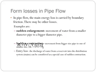
Pipes in parallel: Head loss is a constant i.e. hf=constant The diagram and illustration as discussed in the class = = h h h 1 2 3 f f f The head loss in each pipe between junctions where parallel pipes part and join again must be equal. = + + QT . The total flow rate will equal the s um of individual flow rates. Q Q Q 1 h 2 3 h h f f f = + + Q T r r r 1 2 3 1 n 1 = Q h T f r 3.4 Equivalent Pipe Method for pipe in parallel If we want to replace the system with a single equivalent pipe then: 2 h = r Q f e T h f = Q T r e 2 1 = r e 1 n r 1 or 1 = r e 2 1 n r 1
EXAMPLE 4: For pipe in series Q=constant. Pipe in series as shown on the board. Find Q? Given total head loss as 26m, f =0.01 kc=0.33, where kc is the coefficient of contraction. Consider all losses and use equivalent pipe method. 2 2 2 2 2 5 . 0 . 0 33 v Lv v Lv v 2 = + + + + 1 1 2 1 2 ' ' HT SOLUTION f f 2 2 2 2 g d g g d g g 1.Consider all losses : Write Bernoulli s Equation from reservoir A to B 2 2 = + 26 HT=Entrance loss +head loss due to friction+ head loss due to contraction +head loss due to friction + Exit loss . 0 225 . 0 468 v v 1 2 2 A d = = = 1 1 4 V V V V 2 1 1 1 2 A d 2 2 ( ) 2 2 2 = + = 26 . 0 225 . 0 468 4 . 7 71 V / V V 1 1 1 . 1 = 83 V m = s 1 = = 3 . 0 14 / Q A V 1 A V m s 1 2 2 1.Using equivalent pipe method Neglecting minor losses and calculate pipe constants ' f L . 0 01 122 x = = = 1 d 1 35 51 . r ( . 0 ) 1 5 5 12 12 31 1 = 1136 37 . r 2 For pipe in series 2 1 = = + = 35 51 . 1136 37 . 1171 88 . re r = 2 h r Q f e h 26 f = = = 3 3 . 0 149 / . 0 15 / Q m s m s 1171 . 88 r e Example 5 for pipe in parallel hf=constant Find the head loss across the system shown and discharges in each pipe.
1 SOLUTION r r ' d f L r = 5 12 2 1 = re 1 1 r or 2 1 r 2 1 = . 0 or 114 1 2= 76 95 . ( . 0 ) 114 D(mm) r 305 785.8 28.03 0.036 = 76 = . 95 r e 200 3812.5 61.75 0.016 ( . 0 ) 2= 76 . 95 34 9 . 8 h m f 405 260.0 16.12 0.062 To find the discharge in individual pipes, you have to consider individual pipe Consider 305 mm diameter pipe 0.114 2 2 ' . 0 017 1464 f LV 2 x xV 81 = = 9 . 8 = h m f 305 2 . 9 d g x x . 1 = 46 = / V m 107 s 3 . 0 / Q m s 305 = 3 . 0 049 / Q m s 200 = 3 . 0 186 Q m 405 ( ) = + + 3 . 0 34 / Q Q Q Q m s 305 200 405 T Using Equivalent pipe method hf=constant 2 = h r Q f e T 2 2 = r Q r Q 1 305 e T 95 ( . 0 = ) 2 2 = 76 . 34 785 8 . Q 305 3 . 0 106 / Q m s 305 = 3 . 0 048 / Q m s 200 = 3 . 0 185 / Q m s 405 = 3 . 0 339 . 0 34 / Q m s T