Nested Interrupts Handler and Emulating Instructions Guide
Dive into a comprehensive guide covering nested interrupts handling, emulation of instructions, and register stack operations. Explore detailed instructions and illustrations for an in-depth understanding.

Download Presentation

Please find below an Image/Link to download the presentation.
The content on the website is provided AS IS for your information and personal use only. It may not be sold, licensed, or shared on other websites without obtaining consent from the author. If you encounter any issues during the download, it is possible that the publisher has removed the file from their server.
You are allowed to download the files provided on this website for personal or commercial use, subject to the condition that they are used lawfully. All files are the property of their respective owners.
The content on the website is provided AS IS for your information and personal use only. It may not be sold, licensed, or shared on other websites without obtaining consent from the author.
E N D
Presentation Transcript
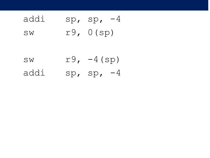
addi sw sp, sp, -4 r9, 0(sp) sw addi r9, -4(sp) sp, sp, -4
int cnt = 9; interrupt: cnt++; program: while (1) cnt--; 8, 9 10, 11, 10 10, 11, 8
.data .word 9 .section .exceptions, ax iHdlr: H1: ldw H2: addi H3: stw eret cnt: r9, 0(r8) r9, r9, 1 r9, 0(r8) cnt++ .text main: movia movi wrctl r8, cnt r9, 1 ctl0, r1 wait: I1: I2: I3: ldw addi stw br r11, 0(r8) r11, r11, -1 r11, 0(r8) wait cnt--
.data cnt: .word 9 .section .exceptions, ax iHdlr: H1: ldw H2: addi H3: stw eret r9, 0(r8) r9, r9, 1 r9, 0(r8) 8, 9 I1 I2 I3 r11 = 9 r11 = 8 cnt = r11 = 8 main: wait: I1: I2: I3: .text movia movi wrctl r8, cnt r9, 1 ctl0, r1 Interrupt: H1, H2, H3 cnt = 9 ldw addi stw br r11, 0(r8) r11, r11, -1 r11, 0(r8) wait
.data cnt: .word 9 .section .exceptions, ax iHdlr: H1: ldw H2: addi H3: stw eret 10, 11, 8 r9, 0(r8) r9, r9, 1 r9, 0(r8) I1 r11 = 9 Interrupt: H1, H2, H3 cnt = 10 main: wait: I1: I2: I3: .text movia movi wrctl r8, cnt r9, 1 ctl0, r1 I2 Interrupt: H1, H2, H3 r11 = 8 cnt = 11 ldw addi stw br r11, 0(r8) r11, r11, -1 r11, 0(r8) wait I3 cnt = r11 = 8
Nested Interrupts handler: # PROLOGUE addi stw stw r2, 4(sp) rdctl r2, ctl1 stw r2, 0(sp) movi r2, 1 wrctl r2, ctl0 sp, sp, -12 ea, 8(sp) # save r2 # save ea # save ctl1 Re-enables interrupts Turn off at least one IRQ request HANDLER CODE ldw r2, 0(sp) wrctl ctl1, r2 ldw r2, 4(sp) ldw ea, 0(sp) addi sp, sp, 12 addi ea, ea, -4 eret # save r2 # save ea
Emulating Instructions mulxuu rC, rA, rB upper 32-bits of 64-bit multiplication result tmp64 = rA x rB rC = %hi(tmp64)
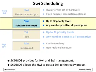
Save all registers on the stack in order Forming a 32-entry word array The value for register rX is at sp + X * 4 yes Hardware interrupt? Handle HW interrupt Read opcode using ea Is it mulxuu? yes Read rA, rB and rC field from opcode Convert them into indexes onto the stack Read rA and rB values from the stack Calculate upper 32 bits of rA * rB Store result onto the stack entry for rC Restore all registers from the stack rC was changed Return from interrupt
.section exceptions .set nobreak .set noat handler: # save all registers on the stack subi sp, sp, 32 * 4
stwio r14,56(sp) stwio r15,60(sp) stwio r16,64(sp) stwio r17,68(sp) stwio r18,72(sp) stwio r19,76(sp) stwio r20,80(sp) stwio r21,84(sp) stwio r22,88(sp) stwio r23,92(sp) stwio r24,96(sp) stwio r25,100(sp) stwio r26,104(sp) stwio r27,108(sp) stwio r28,112(sp) stwio r29,116(sp) stwio r30,120(sp) stwio r31,124(sp) stwio r0,0(sp) stwio r1,4(sp) stwio r2,8(sp) stwio r3,12(sp) stwio r4,16(sp) stwio r5,20(sp) stwio r6,24(sp) stwio r7,28(sp) stwio r8,32(sp) stwio r9,36(sp) stwio r10,40(sp) stwio r11,44(sp) stwio r12,48(sp) stwio r13,52(sp) rX s value is at sp+X*4
Is it a harware interrupt? rdctl et, ctl4 bne et, r0, hwint hwint: HANDLE DEVICES br emuldone
ldw r9, -4(ea) # keep a copy of the opcode add r10, r9, 0 # keep just the lower 16 bits andi r9, r9, 0xffff cmpeqi beq r11, r0, notmulxuu # shift the upper 16 bits into the lower 16 srli r10, r10, 16 # test bit 0 which used to be bit 17 andi r11, r10, 0x1 # if not zero this is not mulxuu bne r11, r0, notmulxuu 0x1383a r11, r9, 0x383a
srli r10,r10,1 # keep just the upper 15 bits of the opcode # rC andi r11, r10, 0x1f # these are the 5 bits indicating rC the destination register slli r11, r11, 2 # multiply by 4 add r11, r11, sp # add the base of the array # rB srli r10, r10, 5 andi r12, r10, 0x1f # keep the bits for rB slli r12, r12, 2 # multiply by 4 add r12, r12, sp # add the base of the array # rA srli r10, r10, 5 andi r13, r10, 0x1f # keep the bits for rA slli r13, r13, 2 # multiply by 4 add r13, r13, sp # add the base of the array
##################################################### # Access input registers ##################################################### # at this point: # r11 points to the entry for rC # r12 points to the entry for rB # r13 points to the entry for rA # read rA and rB into r9 and r10 respectively ##################################################### ldw r9, 0(r13) ldw r10, 0(r12)
##################################################### # Multiplication : No need to understand how this works # end result is in r10 ##################################################### srli r4, r9, 16 # a = (v1 >> 16) & 0xffff; andi r5, r9, 0xffff # b = v1 & 0xffff; srli r6, r10, 16 # c = (v2 >> 16) & 0xffff andi r7, r10, 0xffff # d = v2 & 0xffff; mul srli mul mul add add srli mul add r9, r5, r7 r9, r9, 16 r10, r4, r7 # x= a * d r12, r5, r6 # x1 = c * b r10, r10, r12 r9, r9, r10 # y = y + x r9, r9, 16 r10, r4, r6 # HI = a * c r10, r10, r9 # LO = b * d; # y = ((LO >> 16) & 0xffff) # x = x + x1 # y = (y >> 16) & 0xffff # HI = HI + y ##################################################### # write result onto the corresponding stack entry ##################################################### # store the result to the stack stwio r10, 0(r11) # declare this instruction as executed addi ea, ea, 4
notmulxuu: emuldone: ########################################### # restore all registers from the stack # one value has been changed ########################################### ldwio r0,0(sp) ldwio r1,4(sp) ldwio r2,8(sp) ldwio r3,12(sp) ldwio r4,16(sp) ldwio r5,20(sp) ldwio r6,24(sp) ldwio r7,28(sp) ldwio r8,32(sp) ldwio r9,36(sp) ldwio r10,40(sp) ldwio r11,44(sp) ldwio r12,48(sp) ldwio r13,52(sp) ldwio r14,56(sp) ldwio r15,60(sp) ldwio r16,64(sp) ldwio r17,68(sp) ldwio r18,72(sp) ldwio r19,76(sp) ldwio r20,80(sp) ldwio r21,84(sp) ldwio r22,88(sp) ldwio r23,92(sp) ldwio r24,96(sp) ldwio r25,100(sp) ldwio r26,104(sp) ldwio r27,108(sp) ldwio r28,112(sp) ldwio r29,116(sp) ldwio r30,120(sp) ldwio r31,124(sp) # restore the stack addi sp, sp, 32 * 4 br idone # for hardware interrupts re-execute instruction that was interrupted eadec: subi ea, ea, 4 idone: eret
Save all registers on the stack in order Forming a 32-entry word array The value for register rX is at sp + X * 4 yes Hardware interrupt? Handle HW interrupt Read opcode using ea Is it mulxuu? yes Read rA, rB and rC field from opcode Convert them into indexes onto the stack Read rA and rB values from the stack Calculate upper 32 bits of rA * rB Store result onto the stack entry for rC Restore all registers from the stack rC was changed Return from interrupt
Interrupts on other Processors Vectored Priorities HW ACK Automatic save/restore


")

")