Network Access and Physical Media Structure
Explore the intricate details of network structures including edge hosts, clients, servers, and various access networks such as DSL, cable, and home networks. Learn about connecting end systems, bandwidth considerations, and the technologies like DSLAM and CMTS that power these networks.

Download Presentation

Please find below an Image/Link to download the presentation.
The content on the website is provided AS IS for your information and personal use only. It may not be sold, licensed, or shared on other websites without obtaining consent from the author. If you encounter any issues during the download, it is possible that the publisher has removed the file from their server.
You are allowed to download the files provided on this website for personal or commercial use, subject to the condition that they are used lawfully. All files are the property of their respective owners.
The content on the website is provided AS IS for your information and personal use only. It may not be sold, licensed, or shared on other websites without obtaining consent from the author.
E N D
Presentation Transcript
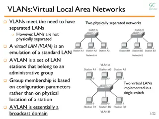
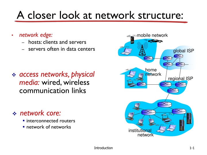
A closer look at network structure: network edge: hosts: clients and servers servers often in data centers mobile network global ISP home network access networks, physical media: wired, wireless communication links regional ISP network core: interconnected routers network of networks institutional network Introduction 1-1
Access networks and physical media Q: How to connect end systems to edge router? residential access nets institutional access networks (school, company) mobile access networks keep in mind: bandwidth (bits per second) of access network? shared or dedicated? Introduction 1-2
Access net: digital subscriber line (DSL) central office telephone network DSL modem splitter DSLAM ISP voice, data transmitted at different frequencies over dedicated line to central office DSL access multiplexer use existing telephone line to central office DSLAM data over DSL phone line goes to Internet voice over DSL phone line goes to telephone net < 2.5 Mbps upstream transmission rate (typically < 1 Mbps) < 24 Mbps downstream transmission rate (typically < 10 Mbps) Introduction 1-3
Access net: cable network cable headend cable modem splitter C O N T R O L V I D E O V I D E O V I D E O V I D E O V I D E O V I D E O D A T A D A T A 5 6 7 8 9 1 2 3 4 Channels frequency division multiplexing: different channels transmitted in different frequency bands Introduction 1-4
Access net: cable network cable headend cable modem splitter cable modem termination system CMTS data, TV transmitted at different frequencies over shared cable distribution network ISP HFC: hybrid fiber coax asymmetric: up to 30Mbps downstream transmission rate, 2 Mbps upstream transmission rate network of cable, fiber attaches homes to ISP router homes share access network to cable headend unlike DSL, which has dedicated access to central office Introduction 1-5
Access net: home network wireless devices to/from headend or central office often combined in single box cable or DSL modem router, firewall, NAT wireless access point (54 Mbps) wired Ethernet (100 Mbps) Introduction 1-6
Enterprise access networks (Ethernet) institutional link to ISP (Internet) institutional router Ethernet switch institutional mail, web servers typically used in companies, universities, etc 10 Mbps, 100Mbps, 1Gbps, 10Gbps transmission rates today, end systems typically connect into Ethernet switch Introduction 1-7
Wireless access networks shared wireless access network connects end system to router via base station aka access point wide-area wireless access provided by telco (cellular) operator, 10 s km between 1 and 10 Mbps 3G, 4G: LTE wireless LANs: within building (100 ft) 802.11b/g (WiFi): 11, 54 Mbps transmission rate to Internet to Internet Introduction 1-8
Physical media bit: propagates between transmitter/receiver pairs physical link: what lies between transmitter & receiver guided media: signals propagate in solid media: copper, fiber, coax unguided media: signals propagate freely, e.g., radio twisted pair (TP) two insulated copper wires Category 5: 100 Mbps, 1 Gpbs Ethernet Category 6: 10Gbps Introduction 1-9
Physical media: coax, fiber fiber optic cable: glass fiber carrying light pulses, each pulse a bit high-speed operation: high-speed point-to-point transmission (e.g., 10 s-100 s Gpbs transmission rate) low error rate: repeaters spaced far apart immune to electromagnetic noise coaxial cable: two concentric copper conductors bidirectional broadband: multiple channels on cable HFC Introduction 1-10
Physical media: radio radio link types: terrestrial microwave e.g. up to 45 Mbps channels LAN (e.g., WiFi) 11Mbps, 54 Mbps wide-area (e.g., cellular) 3G cellular: ~ few Mbps satellite Kbps to 45Mbps channel (or multiple smaller channels) 270 msec end-end delay geosynchronous versus low altitude signal carried in electromagnetic spectrum no physical wire bidirectional propagation environment effects: reflection obstruction by objects interference Introduction 1-11
Chapter 1: roadmap 1.1 what is the Internet? 1.2 network edge end systems, access networks, links 1.3 network core packet switching, circuit switching, network structure 1.4 delay, loss, throughput in networks 1.5 protocol layers, service models 1.6 networks under attack: security 1.7 history Introduction 1-12
The Network Core mesh of interconnected routers the fundamental question: how is data transferred through net? circuit switching: dedicated circuit per call: telephone net packet-switching: data sent thru net in discrete chunks 13
The network core mesh of interconnected routers packet-switching: hosts break application-layer messages into packets forward packetsfrom one router to the next, across links on path from source to Introduction 1-14
Host: sends packets of data host sending function: takes application message breaks into smaller chunks, known as packets, of length L bits transmits packet into access network at transmission rate R link transmission rate, aka link capacity, aka link bandwidth two packets, L bits each 1 2 R: link transmission rate host L (bits) R (bits/sec) time needed to transmit L-bit packet into link packet = = transmission delay 1-15
Packet-switching: store-and-forward L bits per packet 1 3 2 source destination R bps R bps takes L/R seconds to transmit (push out) L-bit packet into link at R bps store and forward: entire packet must arrive at router before it can be transmitted on next link zero propagation delay) one-hop numerical example: L = 7.5 Mbits R = 1.5 Mbps one-hop transmission delay = 5 sec end-end delay = 2L/R (assuming more on delay shortly Introduction 1-16
Packet Switching: queueing delay, loss C R = 100 Mb/s A D R = 1.5 Mb/s B E queue of packets waiting for output link queuing and loss: If arrival rate (in bits) to link exceeds transmission rate of link for a period of time: packets will queue, wait to be transmitted on link packets can be dropped (lost) if memory (buffer) fills up Introduction 1-17
Two key network-core functions routing:determines source- destination route taken by packets routing algorithms forwarding: move packets from router s input to appropriate router output routing algorithm local forwarding table header value output link 0100 0101 0111 1001 1 3 2 2 1 2 3 dest address in arriving packet s header Network Layer 4-18
Network Core: Packet Switching each end-end data stream divided into packets Packets from different users share network resources each packet uses full link bandwidth resources used as needed resource contention: aggregate resource demand can exceed amount available congestion: packets queue, wait for link use store and forward: packet must be completely received before being forwarded packet loss: drop a packet from the queue, when too many packets Bandwidth division into pieces Dedicated allocation Resource reservation 19
Alternative core: circuit switching end-end resources allocated to, reserved for call between source & dest: In diagram, each link has four circuits. call gets 2nd circuit in top link and 1st circuit in right link. dedicated resources: no sharing circuit-like (guaranteed) performance Introduction 1-20
Network Core: Circuit Switching network resources (e.g., bandwidth) divided into pieces pieces allocated to calls resource piece idle if not used by owning call (no lending) dividing link bandwidth into pieces m Frequency Division Multiplexing (FDM) m Time Division Multiplexing (TDM) 21
Circuit switching: FDM versus TDM Example: FDM 4 users frequency time TDM frequency time Introduction 1-22
Packet switching versus circuit switching packet switching allows more users to use network! example: 1 Mb/s link each user: 100 kb/s when active active 10% of time N users 1 Mbps link circuit-switching: 10 users packet switching: with 35 users, probability > 10 active at same time is less than .0004 * * Check out the online interactive exercises for more examples Q: how did we get value 0.0004? Q: what happens if > 35 users ? Introduction 1-23
Packet switching versus circuit switching is packet switching a slam dunk winner? great for bursty data resource sharing simpler, no call setup excessive congestion possible: packet delay and loss protocols needed for reliable data transfer, congestion control Q: How to provide circuit-like behavior? bandwidth guarantees needed for audio/video apps still an unsolved problem (chapter 7) Q: human analogies of reserved resources (circuit switching) versus on-demand allocation (packet-switching)? Introduction 1-24
Internet structure: network of networks End systems connect to Internet via access ISPs (Internet Service Providers) Residential, company and university ISPs Access ISPs in turn must be interconnected. So that any two hosts can send packets to each other Resulting network of networks is very complex Evolution was driven by economics and national policies Let s take a stepwise approach to describe current Internet structure
Internet structure: network of networks Question: given millions of access ISPs, how to connect them together? access net access net access net access net access net access net access net access net access net access net access net access net access net access net access net access net
Internet structure: network of networks Option: connect each access ISP to every other access ISP? access net access net access net access net access net access net access net connecting each access ISP to each other directly doesn t scale: O(N2) connections. access net access net access net access net access net access net access net access net access net
Internet structure: network of networks Option: connect each access ISP to a global transit ISP? Customer and provider ISPs have economic agreement. access net access net access net access net access net access net access net global ISP access net access net access net access net access net access net access net access net access net
Internet structure: network of networks But if one global ISP is viable business, there will be competitors . access net access net access net access net access net access net access net ISP A access net access net ISP B ISP C access net access net access net access net access net access net access net
Internet structure: network of networks But if one global ISP is viable business, there will be competitors . which must be interconnected Internet exchange point access net access net access net access net access net IXP access net access net ISP A IXP access net access net ISP B ISP C access net access net peering link access net access net access net access net access net
Internet structure: network of networks and regional networks may arise to connect access nets to ISPS access net access net access net access net access net IXP access net access net ISP A IXP access net access net ISP B ISP C access net access net regional net access net access net access net access net access net
Internet structure: network of networks and content provider networks (e.g., Google, Microsoft, Akamai ) may run their own network, to bring services, content close to end users access net access net access net access net access net IXP access net access net ISP A Content provider network IXP access net access net ISP B ISP B access net access net regional net access net access net access net access net access net
Internet structure: network of networks Tier 1 ISP Tier 1 ISP Google IXP IXP IXP Regional ISP Regional ISP access ISP access ISP access ISP access ISP access ISP access ISP access ISP access ISP at center: small # of well-connected large networks tier-1 commercial ISPs (e.g., Level 3, Sprint, AT&T, NTT), national & international coverage content provider network (e.g, Google): private network that connects it data centers to Internet, often bypassing tier-1, regional ISPs Introduction 1-33
Tier-1 ISP: e.g., Sprint POP: point-of-presence to/from backbone peering to/from customers Introduction 1-34
traceroute.org Introduction 1-35


")


")