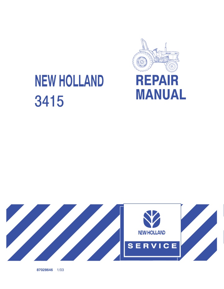
New Holland 3415 Tractor Service Repair Manual Instant Download
New Holland 3415 Tractor Service Repair Manual Instant Download
Download Presentation

Please find below an Image/Link to download the presentation.
The content on the website is provided AS IS for your information and personal use only. It may not be sold, licensed, or shared on other websites without obtaining consent from the author. If you encounter any issues during the download, it is possible that the publisher has removed the file from their server.
You are allowed to download the files provided on this website for personal or commercial use, subject to the condition that they are used lawfully. All files are the property of their respective owners.
The content on the website is provided AS IS for your information and personal use only. It may not be sold, licensed, or shared on other websites without obtaining consent from the author.
E N D
Presentation Transcript
REPAIR MANUAL 3415 1/03 87028646
3415 REPAIR MANUAL CONTENTS SECTION 1 - - ENGINE SYSTEMS SECTION 2 - - FUEL SYSTEMS SECTION 3 - - ELECTRICAL SYSTEM SECTION 4 - - CLUTCH SECTION 5 - - TRANSMISSION SYSTEMS SECTION 6 - - POWER TAKE-OFF SYSTEMS SECTION 7 - - DIFFERENTIAL, REAR AXLE AND BRAKES SECTION 8 - - HYDRAULIC SYSTEM SECTION 9 - - STEERING SYSTEM SECTION 10 - - FRONT AXLE AND RELATED PARTS SECTION 11 - - WHEELS AND TIRES SECTION 12 - - SEPARATING THE TRACTOR 426 -- 1/03 ? 2003 NEW HOLLAND NORTH AMERICA, INC.
SECTION 1 - - ENGINE SYSTEMS - - CHAPTER 1 SECTION 1 - - ENGINE SYSTEMS Chapter 1 - - Engine and Lubrication System CONTENTS Section Description Page 00 000 Engine and Lubrication System Description and Operation . . . . . . . . . . . . . . . . . . . . . . . . . 1-2 00 000 Engine Overhaul . . . . . . . . . . . . . . . . . . . . . . . . . . . . . . . . . . . . . . . . . . . . . . . . . . . . . . . . . . . . . 1-7 00 000 Engine Lubrication System Description . . . . . . . . . . . . . . . . . . . . . . . . . . . . . . . . . . . . . . . . . 1-18 00 000 Engine Lubrication System Overhaul . . . . . . . . . . . . . . . . . . . . . . . . . . . . . . . . . . . . . . . . . . . 1-21 1-1
https://www.ebooklibonline.com Hello dear friend! Thank you very much for reading. Enter the link into your browser. The full manual is available for immediate download. https://www.ebooklibonline.com
SECTION 1 - - ENGINE SYSTEMS - - CHAPTER 1 ENGINE SYSTEM DESCRIPTION AND OPERATION This chapter describes engine overhaul and repairs procedures for the Model 3415 tractor engine. The engine is a four cylinder, four cycle, overhead valve, liquid cooled engine, Figures 1 and 2. 1 2 1-2
SECTION 1 - - ENGINE SYSTEMS - - CHAPTER 1 The engines is identified by a code number, 1, cast into the side of the cylinder block. Engine Identification Tractor Model 1 Horsepower N844L 3415 47.0 19997052 5 Cylinder Head and Valve Train Components The cylinder head assemblies, rocker arms, rocker shaft, push rods, and lifters. incorporates the valve 3 2 The intake manifold, 1, is located on the top of the cylinder head and is separate from the valve cover, 2. The exhaust manifold, 3, is bolted to the left side of the cylinder head. 1 19997053 6 The valve rocker arms and support shaft, 1, are mounted in a separate support casting bolted to the top of the cylinder head. 1 3 2 19997054 7 1-4
SECTION 1 - - ENGINE SYSTEMS - - CHAPTER 1 Cylinder Block Assembly NOTE: This engine is certified to 1999 EPA emission legislation. No one is permitted to repair the engine unless the fuel delivery is unchanged, therefore preserving the emissions replacement of block, short block assembly, smoke set, etc. is not permitted. In that case please use a long block assembly for repairing. performance, eg. The cylinder block assembly contains the pistons, connecting rods, crankshaft, camshaft, timing gears, engine oil pump and dynamic balancer assembly. The engine is equipped with straight connecting rods. The crankshaft is supported on five main bearings. The front bearing is supported in a bore in the front casting of the cylinder block. Allremaining bearings are split liners retained in cast iron holders. The engine incorporates a dynamic balancer assembly, 1, that is bolted to the under side of the block and driven by the crankshaft. 1 19997055 8 1-5
SECTION 1 - - ENGINE SYSTEMS - - CHAPTER 1 Lubrication System The oil pump assembly is located within the idle gear at the front of the block and below and to the left of thecrankshaftasviewedfromthefront.Theoilpump is driven by the crankshaft gear. 2 Oilis picked up from the sump by the intake tube and drawn into the lower side drilling in the block to the oil pump. Oil from the pump flows through passages in the block, past the relief valve, through the oil filter and returns to the main oil gallery in the area of the drilled bolt located on the side of the block. Oil flow in the main oil gallery extends to the main bearings. Oil flow to the main bearings passes through drilled passages in the crankshaft to the connecting rod bearings. 1 19997055 9 Oil from the main oil gallery supplies pressure oil to the dynamic balancer, 1, through a tube, 2, connected to the under side of the block. Pressure oil from the main oil gallery flows through a tube, 3, to the front of the valve rocker shaft to lubricate the rocker arms, valve stems, push rods and tappets. The relief valve, 4, is mounted in the side of the block and intersects the main oil passage. When the oil pressureexceedstheratedpressure,oilisbypassed through the relief valve directly to sump. Thecylinderwalls,pistonsandpistonpinsaresplash lubricated by the crankshaft. 3 4 4 20012873 10 1-6
SECTION 1 - - ENGINE SYSTEMS - - CHAPTER 1 ENGINE OVERHAUL 1 Cylinder Head Removal 1. Open the hood, 1, and remove the side covers, 2. Disconnect the headlight wiring, 3. Remove the hood assembly. 3 2 20012874 11 2. Drain the coolant from the radiator and engine block through the radiator drain cock, 1. 1 20012875 12 3. Remove the air cleaner assembly, 1, along with the air inlet tube, 2, and air outlet tube, 3. 2 4 4. Remove the upper radiator hose, 4, from the cylinder head. 1 3 20012876 13 1-7
SECTION 1 - - ENGINE SYSTEMS - - CHAPTER 1 5. Remove the exhaust muffler and manifold assembly, 1. 1 19997053 14 6. Remove the fuel injection lines, 1, and fuel leakoff line, 3, and cap all openings. 3 7. Remove the injector assemblies, 2. 1 2 20012877 15 8. Remove thermostat. the thermostat housing, 2, and 2 9. Remove the fuel tank and baffle. 1 19997061 16 1-8
SECTION 1 - - ENGINE SYSTEMS - - CHAPTER 1 10. Remove the oil pressure sensor switch, 3. 3 11. Remove the external oil tube banjo bolt, 2, from the front end of the valve rocker shaft. 2 1 19997062 17 12. Remove the air intake manifold, 1. 13. Remove the valve cover assembly, 2. 2 1 19997053 18 14. Remove the valve rocker support, 1, as an assembly. 1 NOTE: Alternately loosen the rocker support bolts a turn at a time to prevent distorting the rocker shaft. 3 15. Remove the valve stem caps, 3, and push rods, 2. NOTE: Keep all valve components in separately marked containers for reassembly in their original position. 2 16. Loosen the cylinder head bolts gradually a half turn at a time to prevent warping of the cylinder head and remove the cylinder head. 19997054 19 1-9
SECTION 1 - - ENGINE SYSTEMS - - CHAPTER 1 Cylinder Head Disassembly 1. Clean the cylinder head and remove any carbon deposits from around the valve heads. 1 2. Using a valve spring compressor, 1, compress the valve spring, 3, and remove the retainer locks, 5. 2 3 3. Release the valve spring compressor and remove the valve spring and retainer, 4. 4 5 4. Remove the valves, 2, from the head and place inanumberedcontainertofacilitateidentification for installing the components in their original location on assembly. 19997063 20 Cylinder Head Inspection and Repair 1. Clean the valve ports using a wire brush and scraper. A 2. Cleanalldirtandresiduefromthegasketsurface using care not to scratch or nick the machined surface. F C D E B 3. Clean the cylinder head in solvent and air dry. 4. Check the head for cracks or damage in the following areas: Valve ports. Valve seats. External cracks in the water jackets. 5. Inspect the gasket surfaces for scratches or nicks which would cause leakage. 1 6. Examine the core hole plugs for rust or signs of leakage. If a plug shows signs of damaging rust or leakage, replace all the plugs in the head. 7. Use a straight edge, 1, and feeler gauge and check the cylinder head for warp in the areas shown, (A -- F). 19997064 21 Resurface or replace the head if warpage is greater than 0.12 mm (0.005 ). 8. Check the push rods for straightness. Replace bent push rods. Do not attempt to straighten. 1-10
SECTION 1 - - ENGINE SYSTEMS - - CHAPTER 1 Valve Seats Examine the valve seats and reface the seat if damaged. 1 Valve seat grinding requires that the seat be ground to the correct width and properly positioned. A valve that extends too deep into the combustion area will result in valve burning and if the valve is recessed too deep into the head it will cause a rapid build-up of carbon deposits. 2 3 22 1. Correct Valve Seat Width: 1.7 - 2.1 mm (0.067 - 0.0826 ) - Seat must strike center of valve face 2. CorrectValveHeadMargin:0.775-1.075mm(0.0305 - 0.0420 ) 3. Angle of Valve Seat: 45_ 1. Check the seat for surface defects. Use a 45 stone if necessary to reface. Grind away only enough material to provide a smooth even seat. 3 150 2. Check the seat width. If necessary, use a 15 stone to lower the seat contact point and use a 75 stone to raise the seat contact point. 1 90 NOTE: Refacing the seat should always be coordinated with refacing of the valve to assure a compression tight fit. 30 0.5 MM (0.020 ) MIN. 2 23 1. Seat angle - 45 Stone 2. Lower Seat Location - 15 Stone 3. Raise Seat Location - 75 Stone 1-11
SECTION 1 - - ENGINE SYSTEMS - - CHAPTER 1 Valves 1. Clean all deposits from the valves using a soft wire brush. Inspect the condition of the valveand discard any that are badly burned, cracked or bent. 2 5 4 6 3 1 24 1. Margin Too Thin 1920 - 0.5 mm (0.002 ) Min. 2120 - 1.0 mm (0.039 ) Min. 2. Bent Valve 3. Pitting 4. Indented 5. Wear or Nicking 6. Burned 2. Using a micrometer, measure the stem diameter at three points A, B, and C. A B C Replace valves if the stem wear diameter is less than the following dimensions: Intake Exhaust 6.84 mm (0.269 ) 6.89 mm (0.271 ) A B C 25 1-12
SECTION 1 - - ENGINE SYSTEMS - - CHAPTER 1 3. If inspection indicates that the valve may be reused, the valve should be ground as shown. IMPORTANT: After grinding the valve and seat, check to assure that the seat contacts the center of the valve face. Using Prussian Blue, lightly coat the valve seat, place the valve in position and rotate the valve slightly while holding a light pressure against thevalve.Ifthe blueis transferredto thecenter ofthe valve face, the contact is correct. 1 2 26 1. 45_ Seat Angle 2. Minimum Valve Margin 0.5 mm (0.002 ) If Prussian Blue is not available, mark the valve face or seat with a soft lead pencil as shown. Rotate the valve slightly in the seat. The penciled lines will be broken at the seat contact area. 1 27 1-13
SECTION 1 - - ENGINE SYSTEMS - - CHAPTER 1 Valve Guides Thoroughly clean the valve guides before attempting to check internal wear. 1 1. Using a small hole gauge, measure the valve guide bore at the top and bottom wear points, 1. 1 28 2. Determine the stem-to-guide clearance by subtracting the stem diameter from the valve guide. Replace the valves if the clearance is more than the specified limits: Exhaust 0.25 mm (0.010 ) Max Intake 0.20 mm (0.008 ) Max 1 3. Replacethecylinderheadifexcessiveclearance is determined. See Specifications. 29 Valve Springs 1. Place the valve springs on a flat surface. Measure the free-length of the spring and squareness. Replace springs that do not meet the following specifications: Standard 1.2 mm (0.047 ) 35.0 mm (1.378 ) Maximum 2.0 mm (0.079 ) 33.5 mm (1.319 ) Out of Round Free Length 30 2. Place the springs in a suitable spring load tester and measure the spring load rating. Replace the springs that do not meet the following load specifications: Minimum 7 kg (15.432 lbs) at 30.4 mm (1.197 ) Standard 8.1 kg (17.857 lbs) at 30.4 mm (1.197 ) 1-14
Suggest: If the above button click is invalid. Please download this document first, and then click the above link to download the complete manual. Thank you so much for reading
SECTION 1 - - ENGINE SYSTEMS - - CHAPTER 1 Rocker Arm Pivots Disassembly 1. Screw a 8M bolt into the front end of the rocker shaft, 1, and pull the rocker shaft out of the support. 3 2. Remove the springs, 3, shims, 4, and rocker arms, 2. 1 2 4 19997065 31 Rocker Arm Pivots Inspection and Repair 1. Inspect the rocker arms and shafts for wear of damage. 1 2. Inspect the valve stem contact area for pitting or wear. Slight wear patterns may be removed using a fine grit stone. 3. Checktheadjustingscrewsfordamagedthreads or excessive wear. Replace any components which are visually worn or damaged. 19997066 4. Usingamicrometer,measurethediameter ofthe rocker arm shaft, 1. 32 Replace the rocker shaft if the wear at any point exceeds the following diameter: Minimum 14.87 mm (0.5854 ) Standard 14.95 - 14.97 mm (0.5886 - 0.5894 ) 5. Using a hole gauge, measure the inside bore diameter of the rocker arm. Subtract the rocker shaft diameter from the rocker arm bore diameter shaft-to-arm clearance. to obtain the Replace the rocker arm and/or shaft assembly if the clearance exceeds specifications: the following Maximum 0.2 mm (0.008 ) Standard 0.032 - 0.068 mm (0.5886 - 0.5894 ) 33 1-15
https://www.ebooklibonline.com Hello dear friend! Thank you very much for reading. Enter the link into your browser. The full manual is available for immediate download. https://www.ebooklibonline.com

