New Holland 8770 Tractor Service Repair Manual Instant Download
New Holland 8770 Tractor Service Repair Manual Instant Download
Download Presentation

Please find below an Image/Link to download the presentation.
The content on the website is provided AS IS for your information and personal use only. It may not be sold, licensed, or shared on other websites without obtaining consent from the author. If you encounter any issues during the download, it is possible that the publisher has removed the file from their server.
You are allowed to download the files provided on this website for personal or commercial use, subject to the condition that they are used lawfully. All files are the property of their respective owners.
The content on the website is provided AS IS for your information and personal use only. It may not be sold, licensed, or shared on other websites without obtaining consent from the author.
E N D
Presentation Transcript
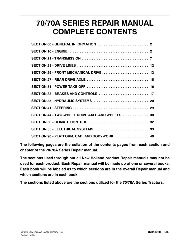
70/70A SERIES REPAIR MANUAL COMPLETE CONTENTS SECTION 00 - GENERAL INFORMATION . . . . . . . . . . . . . . . . . . . . . . . . . . . . . 2 SECTION 10 - ENGINE . . . . . . . . . . . . . . . . . . . . . . . . . . . . . . . . . . . . . . . . . . . . . . 2 SECTION 21 - TRANSMISSION . . . . . . . . . . . . . . . . . . . . . . . . . . . . . . . . . . . . . . . 7 SECTION 23 - DRIVE LINES . . . . . . . . . . . . . . . . . . . . . . . . . . . . . . . . . . . . . . . . . . 12 SECTION 25 - FRONT MECHANICAL DRIVE . . . . . . . . . . . . . . . . . . . . . . . . . . . 12 SECTION 27 - REAR DRIVE AXLE . . . . . . . . . . . . . . . . . . . . . . . . . . . . . . . . . . . . 15 SECTION 31 - POWER TAKE-OFF . . . . . . . . . . . . . . . . . . . . . . . . . . . . . . . . . . . . 16 SECTION 33 - BRAKES AND CONTROLS . . . . . . . . . . . . . . . . . . . . . . . . . . . . . 17 SECTION 35 - HYDRAULIC SYSTEMS . . . . . . . . . . . . . . . . . . . . . . . . . . . . . . . . 20 SECTION 41 - STEERING . . . . . . . . . . . . . . . . . . . . . . . . . . . . . . . . . . . . . . . . . . . . 29 SECTION 44 - TWO-WHEEL DRIVE AXLE AND WHEELS . . . . . . . . . . . . . . . 30 SECTION 50 - CLIMATE CONTROL . . . . . . . . . . . . . . . . . . . . . . . . . . . . . . . . . . . 32 SECTION 55 - ELECTRICAL SYSTEMS . . . . . . . . . . . . . . . . . . . . . . . . . . . . . . . 33 SECTION 90 - PLATFORM, CAB, AND BODYWORK . . . . . . . . . . . . . . . . . . . . 40 The following pages are the collation of the contents pages from each section and chapter of the 70/70A Series Repair manual. The sections used through out all New Holland product Repair manuals may not be used for each product. Each Repair manual will be made up of one or several books. Each book will be labeled as to which sections are in the overall Repair manual and which sections are in each book. The sections listed above are the sections utilized for the 70/70A Series Tractors. 87018730 6/02 2002 NEW HOLLAND NORTH AMERICA, INC. Printed In U.S.A.
SECTION 00 - - GENERAL INFORMATION - - CHAPTER 1 FOREWORD Appropriate service methods and correct repair procedures are essential for the safe, reliable operation of all equipment, as well as the personal safety of the individual performing the repair. This Service Manual provides troubleshooting, overhaul, and pressure-testing instructions using recommended procedures and equipment. Following these instructions will ensure the safe, efficient, and timely completion of the service or repair. There are numerous variations in procedures, techniques, tools, and parts for servicing machines, as well as in the skill of the individual doing the work. This manual cannot possibly anticipate all such variations and provide advice or cautions as to each. Accordingly, anyone who departs from the instructions provided in this manual mustfirstestablishthattheirpersonalsafety,thesafetyofothers,andtheintegrityofthemachinewillnotbecom- promised by the choice of methods, tools or parts. The manual is divided into sections which are subdivided into chapters. Each chapter contains information on general operating principles, detailed inspection, overhaul and, where applicable, specific troubleshooting, spe- cial tools, and specifications. Any reference in this manual to right, left, rear, front, top, or bottom is as viewed from the operator s seat, looking forward. Alldataandillustrationsinthismanualaresubjecttovariationsinbuildspecification.Thisinformationwascorrect at the time of issue, but New Holland policy is one of continuous improvement, and the right to change specifica- tions, equipment, or design at any time, without notice, is reserved. 00-2
SECTION 00 - - GENERAL INFORMATION - - CHAPTER 1 PRECAUTIONARY STATEMENTS PERSONAL SAFETY Throughout this manual and on machine decals, you will find precautionary statements ( CAUTION , WARNING , and DANGER ) followed byspecific instructions.These precautionsare intendedfor thepersonal safety of you and those working with you. Please take the time to read them. CAUTION The word CAUTION is used where a safe behavioral practice according to operating and maintenance instructions and common safety practices will protect the operator and others from accident involvement. WARNING The word WARNING denotes a potential or hidden hazard which has a potential for serious injury. It is used to warn operators and others to exercise every appropriate means to avoid a surprise involvement with machinery. DANGER The word DANGER denotes a forbidden practice in connection with a serious hazard. FAILURE TO FOLLOW THE CAUTION , WARNING , AND DANGER INSTRUCTIONS MAY RESULT IN SERIOUS BODILY INJURY OR DEATH. MACHINE SAFETY Additional precautionary statements ( ATTENTION and IMPORTANT ) are followed by specific instructions. These statements are intended for machine safety. ATTENTION: The word ATTENTION is used to warn the operator of potential machine damage if a certain procedure is not followed. IMPORTANT: The word IMPORTANT is used to inform the reader of something he needs to know to prevent minor machine damage if a certain procedure is not followed. 00-3
https://www.ebooklibonline.com Hello dear friend! Thank you very much for reading. Enter the link into your browser. The full manual is available for immediate download. https://www.ebooklibonline.com
SECTION 00 - - GENERAL INFORMATION - - CHAPTER 1 SAFETY PRECAUTIONS Practically all service work involves the need to drive the tractor. The operator s manual, supplied with each tractor, contains detailed safety precautions relating to driving, operating, and servicing that tractor. These precautions are as applicable to the service technician as they are to the operator and should be read, understood and practiced by all personnel. Hand Protection It is advisable to use a protective cream before work to prevent irritation and skin contamination. After workcleanyourhandswithsoapandwater.Solvents such as mineral spirit and kerosene may harm the skin. Foot Protection Substantialorprotective footwearwith reinforcedtoe caps will protect your feet from falling objects. Additionally, oil-resistant soles will help to avoid slipping. Prior to undertaking any maintenance, repair, overhaul, dismantling or reassembly operations, whether within a workshop facility or in the field, consideration should be given to factors that may have an effect upon safety, not only upon the mechanic carrying out the work, but also upon bystanders. Special Clothing For certain work it may be necessary to wear flame or acid-resistant clothing. PERSONAL CONSIDERATIONS The wrong clothes or carelessness in dress can cause accidents. Check to see that you are suitable clothed. EQUIPMENT CONSIDERATIONS Machine Guards Before using any machine, check to ensure that the machine guards are in position and serviceable. These guards not only prevent parts of the body or clothing coming in contact with the moving parts of the machine, but also ward off objects that might fly off the machine and cause injury. Some jobs require special protective equipment. Skin Protection Used motor oil may cause skin cancer. Follow work practices that minimize the amount of skin exposed and length of time used oil stays on your skin. Lifting Devices Alwaysensurethatliftingequipment,suchaschains, slings, lifting brackets, thoroughly checked before use. If in doubt, select stronger equipment than is necessary. Eye Protection The smallest eye injury may cause loss of vision. Injury can be avoided by wearing eye protection when engaged in chiselling, grinding, discing, welding, and painting. hooks and eyes, are Never stand under a suspended load or raised implement. Breathing Protection Fumes, dust, and paint spray are unpleasant and harmful. These can be respiratory protection. Compressed Air The pressure from a compressed-air line often exceeds 690 bar (100 PSI). It is perfectly safe if used correctly. Any misuse may cause injury. avoided by wearing Hearing Protection Loud noise may damage your hearing, and the greater the exposure the worse the damage. If the noise is excessive, wear ear protection. Neverusecompressedairtoblowdust,filing,anddirt away from your work area unless the correct type of nozzle is fitted. Compressed air is not a cleaning agent; it will only move dust from one place to another. Look around before using an air hose as bystanders may get grit into their eyes, ears, or skin. Lifting Protection Avoidinjurybycorrectlyhandlingcomponents.Make sure you are capable of lifting the object. If in doubt get help. 00-4
SECTION 00 - - GENERAL INFORMATION - - CHAPTER 1 Hand Tools Many cuts, abrasions and injuries are caused by defective tools. Never use the wrong tool for the job, as this generally leads either to some injury or to a poor job. Work cleanly, disposing of waste materialinto proper containers. Locate the fire extinguishers and find out how to operate them. Do not panic - warn those near and raise the alarm. When removing or replacing hardened pins, use a copper or brass drift rather than a hammer. Do not allow or use an open flame near the tractor fuel tank, battery, or component parts. For dismantling, overhaul, and assembly of major and sub-components, always use the Special Service Tools recommended. These will reduce the work effort, labor time, and the repair cost. First Aid In the type of work that mechanics are engaged in, dirt, grease, and fine dusts settle upon the skin and clothing. If a cut, abrasion or burn is disregarded it may become infected within a short time. Seek medical aid immediately. Electricity Electricity has become so familiar in day to day usage, that its potentially dangerous properties are oftenoverlooked.Misuse ofelectricalequipmentcan endanger life. Cleanliness Cleanliness of the tractor hydraulic system is essential for optimum performance. When carrying out service and repairs, plug all hose ends and component connections to prevent dirt entry. Before using any electrical equipment - particularly portable appliances - make a visual check to make sure that the wiring is not worn or frayed and that the plugs and sockets are intact. Make sure you know where the nearest isolating equipment is located. switch for your Clean the exterior of all components before carrying out any form of repair. Dirt and abrasive dust can reducetheefficiencyandworkinglifeofacomponent and lead to costly replacement. high-pressure washer or steam cleaner is recom- mended. GENERAL CONSIDERATIONS Use of a Solvents Usecleaningfluidsandsolventsthatareknowntobe safe. Certain types of fluids can cause damage to components, such as seals, and can cause skin irritation. Solvents should be checked that they are suitable not only for the cleaning of components and individual parts, but also that they do not affect the personal safety of the user. OPERATIONAL CONSIDERATIONS Stop the engine, if at all possible, before performing any service. Place a warning sign on tractors which, due to service or overhaul, would be dangerous to start. Disconnect the battery leads if leaving such a unit unattended. Housekeeping Many injuries result from tripping over or slipping on objects or material left lying around by a careless worker. Prevent these accidents from occurring. If you notice a hazard, don t ignore it - remove it. Do not attempt to start the engine while standing beside the tractor or attempt to bypass the safety start switch. A clean, hazard-free place of work improves the surroundings and daily environment for everybody. Avoid prolonged running of the engine in a closed building or in an area with inadequate ventilation as exhaust fumes are highly toxic. Fire Fire has no respect for persons or property. The destruction that a fire can cause is not always fully realized. Everyone must be constantly on guard. Always turn the radiator cap to the first stop to allow pressure in the system to dissipate when the coolant is hot. Neverworkbeneathatractorwhichisonsoftground. Always take the unit to an area which has a hard working surface, preferably concrete. Extinguish matches, cigars, and cigarettes before throwing them away. 00-5
SECTION 10 - ENGINE - CHAPTER 1 SECTION 10 - - ENGINE Chapter 1 - - Engine and Lubrication System CONTENTS Section Description Page 10 000 Specifications . . . . . . . . . . . . . . . . . . . . . . . . . . . . . . . . . . . . . . . . . . . . . . . . . . . . . . . . . . . . . . . . . . 3 Torque Values . . . . . . . . . . . . . . . . . . . . . . . . . . . . . . . . . . . . . . . . . . . . . . . . . . . . . . . . . . . . . . . 12 Grease and Sealants . . . . . . . . . . . . . . . . . . . . . . . . . . . . . . . . . . . . . . . . . . . . . . . . . . . . . . . . . 14 Special Tools . . . . . . . . . . . . . . . . . . . . . . . . . . . . . . . . . . . . . . . . . . . . . . . . . . . . . . . . . . . . . . . . 15 Description of Operation . . . . . . . . . . . . . . . . . . . . . . . . . . . . . . . . . . . . . . . . . . . . . . . . . . . . . . 16 Cylinder Head Assembly . . . . . . . . . . . . . . . . . . . . . . . . . . . . . . . . . . . . . . . . . . . . . . . . . . . . . . 22 Camshaft Assembly . . . . . . . . . . . . . . . . . . . . . . . . . . . . . . . . . . . . . . . . . . . . . . . . . . . . . . . . . . 22 Crankshaft Assembly . . . . . . . . . . . . . . . . . . . . . . . . . . . . . . . . . . . . . . . . . . . . . . . . . . . . . . . . . 22 Connecting Rods . . . . . . . . . . . . . . . . . . . . . . . . . . . . . . . . . . . . . . . . . . . . . . . . . . . . . . . . . . . . . 22 Pistons . . . . . . . . . . . . . . . . . . . . . . . . . . . . . . . . . . . . . . . . . . . . . . . . . . . . . . . . . . . . . . . . . . . . . 22 Manifolds . . . . . . . . . . . . . . . . . . . . . . . . . . . . . . . . . . . . . . . . . . . . . . . . . . . . . . . . . . . . . . . . . . . 22 Cylinder Block Assembly . . . . . . . . . . . . . . . . . . . . . . . . . . . . . . . . . . . . . . . . . . . . . . . . . . . . . . 22 Timing Gears . . . . . . . . . . . . . . . . . . . . . . . . . . . . . . . . . . . . . . . . . . . . . . . . . . . . . . . . . . . . . . . . 22 Engine Lubrication . . . . . . . . . . . . . . . . . . . . . . . . . . . . . . . . . . . . . . . . . . . . . . . . . . . . . . . . . . . 23 Troubleshooting . . . . . . . . . . . . . . . . . . . . . . . . . . . . . . . . . . . . . . . . . . . . . . . . . . . . . . . . . . . . . . 27 Disassembly and Repair . . . . . . . . . . . . . . . . . . . . . . . . . . . . . . . . . . . . . . . . . . . . . . . . . . . . . . 30 Cylinder Head . . . . . . . . . . . . . . . . . . . . . . . . . . . . . . . . . . . . . . . . . . . . . . . . . . . . . . . . . . . . . . . 30 Cylinder Head Reassembly . . . . . . . . . . . . . . . . . . . . . . . . . . . . . . . . . . . . . . . . . . . . . . . . . . . . 42 Additional Information . . . . . . . . . . . . . . . . . . . . . . . . . . . . . . . . . . . . . . . . . . . . . . . . . . . . . . . . . 45 Crankcase Front Cassette Seal . . . . . . . . . . . . . . . . . . . . . . . . . . . . . . . . . . . . . . . . . . . . . . . . 47 Parts Affected . . . . . . . . . . . . . . . . . . . . . . . . . . . . . . . . . . . . . . . . . . . . . . . . . . . . . . . . . . . . . . . 47 Additional Information . . . . . . . . . . . . . . . . . . . . . . . . . . . . . . . . . . . . . . . . . . . . . . . . . . . . . . . . . 47 Removal of Old Style Seal and Installation of the New Cassette Seal . . . . . . . . . . . . . . . . 47 Front Cassette Seal Removal . . . . . . . . . . . . . . . . . . . . . . . . . . . . . . . . . . . . . . . . . . . . . . . . . . 53 10-1
SECTION 10 - ENGINE - CHAPTER 1 Engine Front Cover and Timing Gear . . . . . . . . . . . . . . . . . . . . . . . . . . . . . . . . . . . . . . . . . . . 58 Oil Pan . . . . . . . . . . . . . . . . . . . . . . . . . . . . . . . . . . . . . . . . . . . . . . . . . . . . . . . . . . . . . . . . . . . . . 60 Connecting Rods, Bearings, Pistons and Rings . . . . . . . . . . . . . . . . . . . . . . . . . . . . . . . . . . . 61 Cylinder Block Overhaul . . . . . . . . . . . . . . . . . . . . . . . . . . . . . . . . . . . . . . . . . . . . . . . . . . . . . . . 64 Piston Assembly Installation . . . . . . . . . . . . . . . . . . . . . . . . . . . . . . . . . . . . . . . . . . . . . . . . . . . 69 Main Bearings, Flywheel and Crankshaft . . . . . . . . . . . . . . . . . . . . . . . . . . . . . . . . . . . . . . . . 70 Rear Cover Plate . . . . . . . . . . . . . . . . . . . . . . . . . . . . . . . . . . . . . . . . . . . . . . . . . . . . . . . . . . . . . 72 Oil Pump . . . . . . . . . . . . . . . . . . . . . . . . . . . . . . . . . . . . . . . . . . . . . . . . . . . . . . . . . . . . . . . . . . . . 75 Oil Filter Support Assembly . . . . . . . . . . . . . . . . . . . . . . . . . . . . . . . . . . . . . . . . . . . . . . . . . . . . 77 Crankshaft . . . . . . . . . . . . . . . . . . . . . . . . . . . . . . . . . . . . . . . . . . . . . . . . . . . . . . . . . . . . . . . . . . 78 Camshaft . . . . . . . . . . . . . . . . . . . . . . . . . . . . . . . . . . . . . . . . . . . . . . . . . . . . . . . . . . . . . . . . . . . 82 Engine Timing Gears . . . . . . . . . . . . . . . . . . . . . . . . . . . . . . . . . . . . . . . . . . . . . . . . . . . . . . . . . 84 Engine Compression Test . . . . . . . . . . . . . . . . . . . . . . . . . . . . . . . . . . . . . . . . . . . . . . . . . . . . . 85 Test Procedure . . . . . . . . . . . . . . . . . . . . . . . . . . . . . . . . . . . . . . . . . . . . . . . . . . . . . . . . . . . . . . 85 Test Reading . . . . . . . . . . . . . . . . . . . . . . . . . . . . . . . . . . . . . . . . . . . . . . . . . . . . . . . . . . . . . . . . 85 Test Conclusion . . . . . . . . . . . . . . . . . . . . . . . . . . . . . . . . . . . . . . . . . . . . . . . . . . . . . . . . . . . . . . 85 10-2
SECTION 10 - ENGINE - CHAPTER 1 SPECIFICATIONS TRACTOR MODEL 8670/8670A 8770*/8770A 8870/8870A 8970/8970A NO. OF CYLINDERS 6 IN-LINE 6 IN-LINE 6 IN-LINE 6 IN-LINE BORE (in.) (mm) 4.4 111.8 4.4 111.8 4.4 111.8 4.4 111.8 STROKE (in.) (mm) 5.0 127.0 5.0 127.0 5.0 127.0 5.0 127.0 DISPLACEMENT (cu in) (L) 456 7.5 456 7.5 456 7.5 456 7.5 COMPRESSION RATIO 17.5-1 17.5-1 17.5-1 17.5-1 TURBOCHARGED Yes Yes Yes Yes INTERCOOLED No No*, Yes Yes Yes FIRING ORDER 153624 153624 153624 153624 LOW IDLE SPEED RPM 900 +/- 25 900 +/- 25 815 +/- 25 815 +/- 25 HIGH IDLE SPEED RPM 2305 +/- 25 2305 +/- 25 2305 +/- 25 2305 +/- 25 RATED ENGINE SPEED RPM 2100 2100 2100 2100 PTO HORSEPOWER 145 160 180 210 CYLINDER BLOCK Taper of Cylinder Bore 0.025 mm (0.001 ) Repair Limit 0.127 mm (0.005 ) Wear Limit Cylinder Bore Out of Round 0.03 mm (0.0015 ) Repair Limit 0.127 mm (0.005 ) Wear Limit Cylinder Bore Diameters 111.778 - 111.841 mm (4.4007 - 4.4032 ) Rear Oil Seal Retainer Bore Diameter 140.77 - 140.87 mm (5.542 - 5.546 ) Block to Head Surface Flatness 0.08 mm (0.003 ) in any 152 mm (6 ) 0.03 mm (0.001 ) in any 25.40 mm (1 ) * Units built after Jan. 1996 are intercooled. 10-3
SECTION 10 - ENGINE - CHAPTER 1 70-110-1853 1 10-17
SECTION 10 - ENGINE - CHAPTER 1 70-110-1842 2 Left Side View (70 Series) Turbocharger Engine oil filter Engine oil dipstick Engine oil filler cap 1. 2. 3. 4. Coolant expansion chamber Air conditioning compressor Coolant conditioning filter 5. 6. 7. 10-18
SECTION 10 - ENGINE - CHAPTER 1 70-110-1843 3 Right Side View (70 Series) Radiator Alternator Bosch inline fuel injection pump Throttle control cable Fuel shutoff solenoid 1. 2. 3. 4. 5. Fuel filter element Starter motor Diesel fuel hand priming pump Muffler 6. 7. 8. 9. 10. Dry air filter 10-19
SECTION 10 - ENGINE - CHAPTER 1 50015837 4 Left Side View (70A Series) Turbocharger Engine oil filter Engine oil dipstick Engine oil filler cap 1. 2. 3. 4. Coolant expansion chamber Air conditioning compressor Coolant conditioning filter 5. 6. 7. 10-20
SECTION 10 - ENGINE - CHAPTER 1 50015835 5 Right Side View (70A Series) Radiator Alternator Bosch inline fuel injection pump Throttle control cable Fuel shutoff solenoid 1. 2. 3. 4. 5. Fuel filter element Starter motor Diesel fuel hand priming pump Muffler 6. 7. 8. 9. 10. Dry air filter 10-21
SECTION 10 - ENGINE - CHAPTER 1 CYLINDER HEAD ASSEMBLY The cylinder head incorporates valves and springs with the valve rocker arm shaft assembly bolted to thecylinderblockthroughthecylinderhead.Cylinder head retaining bolts are evenly spaced with a six-point pattern around each cylinder. This ensures an even clamping load across the cylinder head area. CONNECTING RODS The wedge- or teepee-shaped connecting rods are designed to reduce the reciprocating weight at the piston end and provide increased bearing area atthe piston pin. The connecting rods are assembled as a matched set to each engine attached to the crankshaft by means of insert-type copper/lead or aluminum tin alloy bearings. The intake and exhaust manifolds are bolted to the head. The intake manifold is mounted on the right-hand side of the engine with the injectors mounted outside the rocker cover. The exhaust manifold is mounted on the left-hand side of the engine, water outlet connections and thermostats being attached to the front of the cylinder block directly behind the radiator. The small end of the connecting rod is fitted with a replaceable bronze bushing, through which a free-floating piston pin is fitted. The steel pin is held in place within the piston by two snap rings. PISTONS Pistons of increased weight and strength are constructed of an aluminium silicon alloy with an iron insert for the top ring and on the Models 8870 and 8970 the second ring. The combustion chamber is recessed into the piston crowns. Valve guides are integral in the cylinder head and valves with oversized stems are available in service. All valves are fitted with positive valve rotators, with both intake and exhaust valves using umbrella-type oil seals. Valve lash is maintained by adjustment of the self-locking adjusting screw mounted at each of the rock arms. Each piston has two compression rings and one oil control ring to reduce friction and increase positive sealing. All rings are located above the piston pin. MANIFOLDS The intake manifold is aluminum and is a plenum type to provide better flow into the engine. Opposing manifolds ensure minimum heat transfer to the intake manifold. The intake manifold is tapped for an ether cold starting aid. CAMSHAFT ASSEMBLY The camshaft runs in 5 replaceable bearings. The camshaft drive gear is in mesh and driven by the camshaft idler gear and crank shaft timing gear. Camshaft end thrust is controlled by a thrust plate boltedtotheblockandlocatedbetweenthecamshaft gear and the front camshaft journal. CYLINDER BLOCK ASSEMBLY The cylinder block is an alloy cast iron with deep cylinder skirts and water jackets for cooling the cylinders. The cylinder bores are machined integral with the cylinder block during the manufacturing process. They can be bored oversize for the fitment of sleeves or oversized pistons, which are available in Parts. A helical gear is mounted on the rear of the camshaft and drives the engine oil lubrication pump mounted forward of the flywheel. CRANKSHAFT ASSEMBLY The crankshaft assembly is made of steel and is supported in the cylinder block by 7 main bearings. End thrust is controlled by a thrust bearing incorporated in the center main bearing of the crankshaft. A crankshaft dampener to control torsionalvibrationisfittedexternallytothecrankshaft to ensure smooth running. Front and rear crankshaft oil seals are a one-piece design for long life and durability. TIMING GEARS The crankshaft timing gear is heated and press fitted onto the front of the crankshaft to a high degree of accuracy during manufacturing. precise timing to be maintained during the life of the engine. The crankshaft drives the camshaft idler gear which is attached to the front of the cylinder block. The idler gear then drives the camshaft and the injection pump via meshing helical gears. This enables 10-22
SECTION 10 - ENGINE - CHAPTER 1 70-130-1844 6 ENGINE LUBRICATION The lubrication of the engine is maintained by a rotor-type 22 GPM oil pump mounted in the rear of the engine block, 1, forward of the flywheel on the left-hand side of the engine. 70-130-1845 7 10-23
SECTION 10 - ENGINE - CHAPTER 1 The oil pump is driven from the rear of the camshaft and draws oil from the oil pan through a suction tube and screen assembly. 70-130-1846 8 A spring-loaded regulating valve is integral with the oil filter base, 1, mounted on the left-hand side of the engine block. The spring, 3, and valve, 2, are accessed by removing a retaining plug, 4. The spin-type oil filter mounted on the left-hand side of the engine is easily accessible. Oil flows from the filter to the main oil gallery which runs the length of the cylinder block and intersects the camshaft follower chamber. 70-130-1847 9 The main gallery also supplies oil to the crankshaft main bearings, connecting rods, big end and small end bearings. The underside of the the pistons and pins are lubricated by oil pressure jets mounted adjacenttoeachmainjournalhousing.Thecamshaft gear bushing is pressure lubricated through a drilled passage from the front main bearing. The gear has small oil passages machined on both sides allowing excess oil to escape. 70-130-1848 10 10-24
Suggest: If the above button click is invalid. Please download this document first, and then click the above link to download the complete manual. Thank you so much for reading
SECTION 10 - ENGINE - CHAPTER 1 Timing gears are lubricated by splashed oil from the cam follower chamber and the pressure lubricated camshaft drive gear bushing. 70-110-1849 11 An intermittent flow of oil is directed to the valve rocker arm shaft assembly via a drilled passage in the cylinder block. This is located vertically above #1 camshaft bearing, 1, and aligns to a hole in the cylinder head. The rotation of the camshaft allows a controlled intermediate flow of lubrication. 70-110-1850 12 The turbocharger is supplied with oil from the oilfilter support housing mounted on the left-hand side of the engine. 70-110-1851 13 10-25
https://www.ebooklibonline.com Hello dear friend! Thank you very much for reading. Enter the link into your browser. The full manual is available for immediate download. https://www.ebooklibonline.com

