New Holland 9080L H Grape Harvester Service Repair Manual Instant Download
New Holland 9080L H Grape Harvester Service Repair Manual Instant Download

Download Presentation

Please find below an Image/Link to download the presentation.
The content on the website is provided AS IS for your information and personal use only. It may not be sold, licensed, or shared on other websites without obtaining consent from the author. If you encounter any issues during the download, it is possible that the publisher has removed the file from their server.
You are allowed to download the files provided on this website for personal or commercial use, subject to the condition that they are used lawfully. All files are the property of their respective owners.
The content on the website is provided AS IS for your information and personal use only. It may not be sold, licensed, or shared on other websites without obtaining consent from the author.
E N D
Presentation Transcript
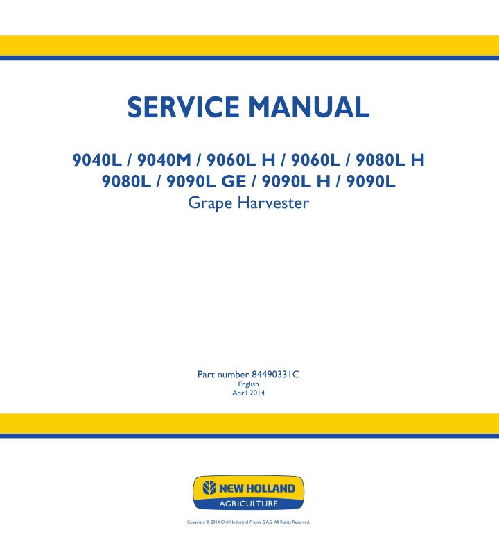
SERVICE MANUAL SERVICE MANUAL 9040L / 9040M / 9060L H / 9060L / 9080L H 9080L / 9090L GE / 9090L H / 9090L Grape Harvester 9040L - 9090L 9060L H - 9090L H 9040M 9090L GE Grape Harvester 1/2 Part number 84490331C English April 2014 Part number 84490331C Copyright 2014 CNH Industrial France S.A.S. All Rights Reserved.
SERVICE MANUAL 9040L 9040M 9060L 9080L 9090L 84490331C 27/03/2014 EN
Link Product / Engine Product Market Product Europe International Region Europe International Region International Region Europe Europe International Region Europe International Region Engine 9040L 9040L null [HAG00690K00002 - ] null [HAG00690K00002 - ] 9080L 9080L 9090L 9090L 9040M 9040M F4HE9484 F4HE9484 F4HE9687 F4HE9687 F4HE9687 F4HE9687 F4HE9687 F4HE9687 F4HE9484 F4HE9484 84490331C 27/03/2014
https://www.ebooklibonline.com Hello dear friend! Thank you very much for reading. Enter the link into your browser. The full manual is available for immediate download. https://www.ebooklibonline.com
Contents INTRODUCTION Rear axle system........................................................................ 27 [27.100] Powered rear axle.................................................................. 27.1 Hydrostatic drive......................................................................... 29 [29.218] Pump and motor components...................................................... 29.1 [29.202] Hydrostatic transmission ........................................................... 29.2 Brakes and controls .................................................................... 33 [33.202] Hydraulic service brakes ........................................................... 33.1 Hydraulic systems....................................................................... 35 [35.000] Hydraulic systems.................................................................. 35.1 [35.300] Reservoir, cooler, and filters........................................................ 35.2 [35.610] Machine leveling control system ................................................... 35.3 [35.946] Frame positioning lifting............................................................ 35.4 [35.903] Shaking hydraulic system.......................................................... 35.5 [35.904] Cleaning hydraulic system ......................................................... 35.6 [35.952] Destemmer system ................................................................ 35.7 [35.930] Conveyor receiver system ......................................................... 35.8 [35.736] Boom hydraulic system ............................................................ 35.9 Frames and ballasting................................................................. 39 [39.100] Frame .............................................................................. 39.1 Steering..................................................................................... 41 [41.101] Steering control .................................................................... 41.1 Electrical systems....................................................................... 55 [55.000] Electrical system ................................................................... 55.1 [55.100] Harnesses and connectors......................................................... 55.2 [55.425] Boom, dipper, and bucket control system.......................................... 55.3 84490331C 27/03/2014
[55.924] Cab grape harvesting controls ..................................................... 55.4 [55.408] Warning indicators, alarms, and instruments ...................................... 55.5 [55.DTC] FAULT CODES.................................................................... 55.6 Grape harvester shaking ............................................................. 56 [56.301] Shaking control..................................................................... 56.1 [56.304] Connecting rods, front plates, and shakers ........................................ 56.2 [56.305] Adjustable width system ........................................................... 56.3 Cleaning.................................................................................... 74 [74.200] Upper extractors ................................................................... 74.1 [74.204] Lower extractors ................................................................... 74.2 84490331C 27/03/2014
INTRODUCTION 84490331C 27/03/2014 1
INTRODUCTION Foreword 9000 L 9040M INT --- WE INT --- WE IMPORTANT INFORMATION All repair and maintenance operations described in this manual must be carried out exclusively by the New Holland Service network, strictly complying with the instructions provided and using specific tools as required. Any operator who carries out the operations specified in this document without complying strictly with the instructions provided shall be personally liable for the damages that may result. The manufacturer and all organizations in its distribution chain, including, without limitation, national, regional, and local dealers, do not accept any liability for damages resulting from a malfunction of parts and/or components not ap- proved by the manufacturer and used for maintenance operations and/or repair of products manufactured or marketed by the manufacturer. In no case is a warranty granted to the product manufactured or marketed by the manufacturer in case of damage caused by improper operation of parts and/or components not approved by the manufacturer. No reproduction, partial or complete, of the text or illustrations is permitted. 84490331C 27/03/2014 3
INTRODUCTION Foreword Technical Information This information in this manual has been structured using a unique coding environment. This is the way in which technical information is created, stored and retrieved in the Technical Information Database. The location (on the machine) has been coded using SAP coding to align locations with the warranty system. The coding classifies all information in three ways. The first category is the Location, the second category is the Information Type and the third category is the Product: LOCATION - is the component or function on the machine, that the piece of technical information is going to describe e.g., Fuel tank. INFORMATION TYPE - is the piece of technical information that has been written for a particular component or function on the machine e.g. Capacity would be a type of Technical Data that would describe the amount of fuel held by the Fuel tank. PRODUCT - is the model that the piece of technical information is written for. Every piece of technical information will have those 3 categories attached to it. You will be able to use any combination of those categories to find the right piece of technical information you need to resolve that customers concern on his machine. That information could be: the description of how to remove the cylinder head a table of specifications for a hydraulic pump a fault code a troubleshooting table a special tool How to Use this Manual This manual is divided into Sections. Each Section is then divided into Chapters. Contents pages are included at the beginning of the manual, then inside every Section and inside every Chapter. An alphabetical Index is included at the end of a Chapter. Page number references are included for every piece of technical information listed in the Chapter Contents or Chapter Index. Each Chapter is divided into four Information types: Technical Data (specifications) for all the mechanical, electrical or hydraulic devices, components and, assemblies. Functional Data (how it works) for all the mechanical, electrical or hydraulic devices, components and assemblies. Diagnostic Data (fault codes, electrical and hydraulic troubleshooting) for all the mechanical, electrical or hydraulic devices, components and assemblies. Service data (remove disassembly, assemble, install) for all the mechanical, electrical or hydraulic devices, com- ponents and assemblies. 84490331C 27/03/2014 4
INTRODUCTION Basic instructions 9000 L 9040M INT --- WE INT --- WE SHIMMING For each adjustment operation, select adjusting shims, individually measure using a micrometer, then add up the recorded values. Do not rely on measuring the entire shimming set, which may be incorrect, and do not rely on the rated value indicated on each shim. ROTATING SHAFT SEALS For correct rotating shaft seal installation, proceed as follows: Before assembly, allow the seal to soak for at least thirty minutes in the oil it will be sealing. Thoroughly clean the shaft, and check that the working surface on the shaft is undamaged. Fit the lip seal toward the fluid. If you are fitting a hydrodynamic lip seal, the grooves should be oriented so that the fluid is directed toward the inner side of the seal (take the shaft direction of rotation into consideration). Coat the lip seal with a thin layer of lubricant (use oil rather than grease), then fill the gap between the lip seal and the dust lip seal of the double-lip seals with grease. Insert the seal into its seat and press down using a flat punch. Do not tap the seal with a hammer or mallet. During assembly, make sure that the seal is fitted perpendicularly to its seat. Once this operation is completed, check to make sure that the seal is in contact with the bearing stop, if required. To prevent damaging the lip seal on the shaft, fit an appropriate protective guard during installation. "O" RINGS Lubricate the "O" rings before fitting them into the seats. This prevents them from overturning and twisting, which would make them ineffective. SEALING COMPOUNDS Apply one of the following sealing compounds to the mating surfaces marked with an X: Silmate RTV, Rhodorsil CAF 1, or Loctite Plastic Gasket. Before applying the sealing compound, prepare the surfaces as follows: Remove any dirt using a metal brush. Thoroughly degrease the surfaces using one of the following cleaning agents: trichloroethylene, gasoline, or a water and soda solution. SPLIT PINS When fitting split pins, make sure that the pin notch is positioned in the direction of the force required to stress the pin. Spiral split pins do not require special positioning. 84490331C 27/03/2014 8
INTRODUCTION PROTECTING THE ELECTRONIC/ELECTRICAL SYSTEMS DURING CHARGING OR WELD- ING To avoid damaging the electronic/electrical systems, always follow the safety instructions below: 1. Never make or break any of the charging circuit connections, including the battery connections, when the engine is running. 2. Never short any of the charging components to ground. 3. Always disconnect the ground cable from the battery before arc welding on the machine or any header attached to the machine. Position the welder ground clamp as close to the welding area as possible. If welding in close proximity to a computer module, the module should be removed from the machine. Never allow welding cables to lay on, near, or across any electrical wiring or electronic component while welding is in progress. 4. Always disconnect the negative cable from the battery when using a battery charger to carry out charging proce- dures on the machine. NOTICE: If welding has to be carried out on the machine or the header (if it is attached), disconnect the battery ground cable from the machine battery. The electronic monitoring system and charging system will be damaged if this is not done. Remove the battery ground cable. Reconnect the cable when welding is completed. WARNING Battery acid causes severe burns. Batteries contain sulfuric acid. Avoid contact with skin, eyes or clothing. Antidote - EXTERNAL: flush with water. INTERNAL: drink large quantities of water or milk. Follow with milk of magnesia, beaten egg or vegetables oil. Call physician immediately. EYES: flush with water for 15 minutes and get prompt medical attention. 84-110 84490331C 27/03/2014 9
SERVICE MANUAL Rear axle system 9040L 9040M 9060L 9080L 9090L 84490331C 27/03/2014 27
Rear axle system - Powered rear axle Rear axle - Transform - Changing the rear track - 9040L 9060L 9080L 9090L INT --- WE INT --- WE INT --- WE INT --- WE NOTE: To change the rear track of the machine by 160 mm (6.3 in), you must turn over the wheel arm fastening bearings. The bearings are moved by 40 mm (1.6 in). 1. Remove the corresponding rear wheel. To do this: Apply the parking brake. Lift the machine using its standalone system. Place a cubed wooden block measuring A = 450 mm (17.7 in) under the rear wheel arm pivot. Lower the machine using its standalone system until the wheel is just off the ground. Shut down the engine. Remove the wheel. 2. Remove the pin (1) of the height stop telescopic tube (2). 1 COIL11GRH020A0B 3. Place a mobile lifting device under the wheel arm (3). 4. Remove the 4 fixing screws (4) from the 2 fastening bearings (5). 2 COIL11GRH021A0B 5. Mark the position of the spacer rings (6). ATTENTION: When reassembling, you must put spacer rings of the same thickness under each bearing. 84490331C 27/03/2014 27.1 [27.100] / 3
Rear axle system - Powered rear axle 6. Remove the spring retaining rings (7) and pull out the bearings (5). 3 COIL11GRH022A0B 7. Fit the bearings (8) onto the wheel arms at the required track width. Position A = wide track. Position B = narrow track. 8. Replace the spring retaining rings (7). 9. Replace the screws (4), inserting the corresponding spacer rings. The tightening torque of the screws (4) is 650 N m (5753.0 lb in). 4 COIL11GRH023A0B NOTE: The diagrams show the positions of the right-hand wheel arm. The bearings are always fitted in the same holes located towards the outside of the machine. To change the track width, the bearings are simply turned over. For information, the other holes are not used. 10. Replace the pin (1) of the height stop tube according to the desired track width. Position A = wide track, the spacer (9) will be on the outside of the chassis. Position B = narrow track, the spacer (9) will be on the inside of the chassis. 5 COIL11GRH024A0B 11. Remove the mobile lifting device. 12. Replace the wheel. The tightening torque of the wheel is 700 N m (6195.5 lb in). 13. Start the engine and raise the machine using its hy- draulic system. Remove the wooden wedge. 84490331C 27/03/2014 27.1 [27.100] / 4
Rear axle system - Powered rear axle 14. Adjust the side stops of the harvesting equipment. The diagram shows how the stop is fitted when the machine track is in the wide position. The spacer ring (10) is fitted inside the bracket. When the machine track is in the narrow position, this spacer ring (10) must be fitted on the outside of the bracket. The 2 spacer rings are both on the outside of the bracket. 6 COIL11GRH025A0B NOTE: The swinging of the harvesting machine will therefore be reduced. 84490331C 27/03/2014 27.1 [27.100] / 5
Hydrostatic drive - Pump and motor components Pump - Remove - Forward control pump- NOTE: When removing the hydraulic piping, have a suitable container readily available to capture any residual hy- draulic oil. 1. Remove the shaker control pump. (see instructions) Hydraulic systems - Remove - Shaker control pump - (35.000). 2. Remove the cleaning control pump. (see instructions) Hydraulic systems - Remove - Cleaning control pump - (35.000). 3. Unscrew the four screws (2) from the inside of the ma- chine to remove the connection block (3). This block will remain at the end of the hoses. NOTE: Recover the O-rings located between the block (3) and the HP block (5). 4. Disconnect all the hoses (4) from the HP block (5). 5. Disconnect all the electrical cables (6) from the HP block (5). 6. Take out the HP block (5) by removing the four fixing screws. ATTENTION: The component weighs approximately 45 kg (99.2 lb). Install a suitable lifting device. 1 COIL10GRH444A0B 7. Disconnect all the hoses (7) from the pump (1). 8. Disconnect the two electrical cables (8) from the servo- control unit. 9. Remove the four screws (9) and pull the pump (1) out. ATTENTION: The component weighs approximately 83 kg (183.0 lb). Install a suitable lifting device. 2 COIL10GRH445A0B 10. Remove the union installations (10) and plug the pump ports. 84490331C 27/03/2014 29.1 [29.218] / 3
Hydrostatic drive - Pump and motor components 11. Unscrew the screw (11) and remove the sleeve (12). 3 COIL10GRH446A0B 84490331C 27/03/2014 29.1 [29.218] / 4
Suggest: If the above button click is invalid. Please download this document first, and then click the above link to download the complete manual. Thank you so much for reading
Hydrostatic drive - Pump and motor components Pump - Install - Forward control pump- NOTE: The component weighs approximately 83 kg (183.0 lb). Install a suitable lifting device. 1. Unplug the pump ports to fit the union installations (2). 2. Fit the drive shaft (3)sleeve. To do this: Slide the sleeve (3) onto the pump shaft (1) until the external side is aligned with the end of the shaft. Tighten the screw (4) to a torque of 210 N m (1858.7 lb in). 1 COIL10GRH446A0C 3. Slide the pump (1) onto the motor output and secure it using the four screws (5). NOTE: The screws (5) are screwed down with normal thread lock fluid and tightened to a torque of 200 N m (1770.1 lb in). 4. Connect all the hoses (5) to the pump, except the drainage hose (7). 2 COIL10GRH447A0B 5. Connect the pump servo-control electrical cables. NOTE: The forward motion circuit will not function correctly unlesstheelectricalconnectionscorrespondtothoseinthe diagram below. 3 COIL10GRH448A0B 6. Position the hydraulic HP block (8) under the pump (1)and secure it using four screws (10) tightened to a torque of 120 N m (1062.1 lb in). NOTE: Check the condition and position of the O-rings between the HP block and the pump. 7. Connect all the hoses (11) to the HP block (8). 84490331C 27/03/2014 29.1 [29.218] / 5
https://www.ebooklibonline.com Hello dear friend! Thank you very much for reading. Enter the link into your browser. The full manual is available for immediate download. https://www.ebooklibonline.com