New Holland 9884 Tractor Service Repair Manual Instant Download
New Holland 9884 Tractor Service Repair Manual Instant Download

Download Presentation

Please find below an Image/Link to download the presentation.
The content on the website is provided AS IS for your information and personal use only. It may not be sold, licensed, or shared on other websites without obtaining consent from the author. If you encounter any issues during the download, it is possible that the publisher has removed the file from their server.
You are allowed to download the files provided on this website for personal or commercial use, subject to the condition that they are used lawfully. All files are the property of their respective owners.
The content on the website is provided AS IS for your information and personal use only. It may not be sold, licensed, or shared on other websites without obtaining consent from the author.
E N D
Presentation Transcript
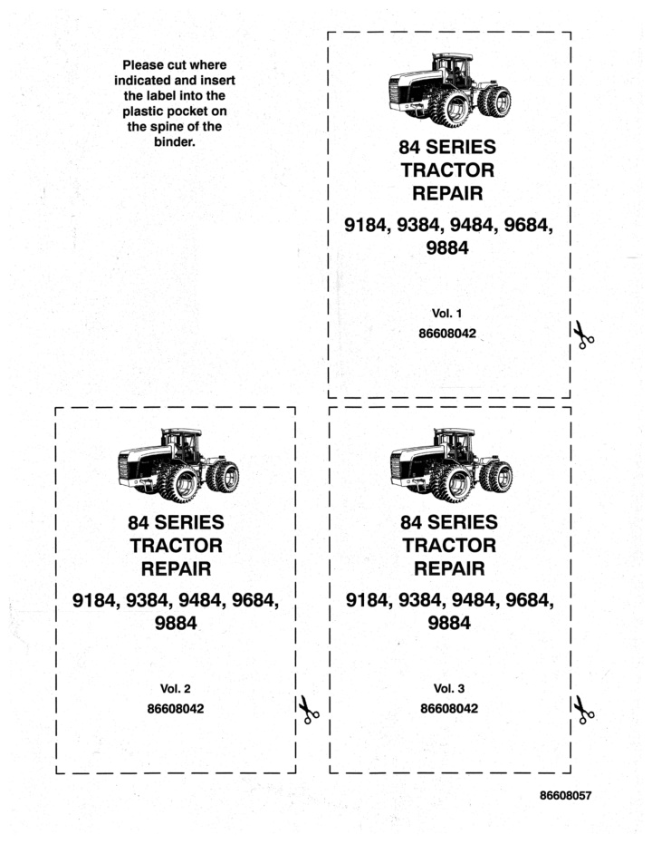
r--- -------, Please cut where indicated and insert the label into the plastic pocket on the spine' of the binder. 84 SERIES TRACTOR REPAIR 9184,9384,9484,9684, 9884 Vol. 1 86608042 _______ ...1 L __ r-----------, r-----------, I I I I I I I REPAIR : 9184, 9384, 9484, 9684, I 9884 I I I I I L ____ ' _____ ...1 84 SERIES TRACTOR 84 SERIES TRACTOR REPAIR 9184,9384,9484,9684, 9884 Vol. 2 86608042 Vol. 3 86608042 ~ . . ___ ...1 L __ . ____ 86608057
NEW HOLLAND 9184 9384 9484 9684 9884 . - ;} Section 1 - Engine REPAIR MANUAL SERVICE I Reprinted I 86608043 3/00
84 SERIES TRACTOR REPAIR MANUAL CONTENTS ~ SECTION 1 - ENGINE SECTION 2 - FUEL SYSTEM SECTION 3 - ELECTRICAL SYSTEM SECTION 4 - TRANSMISSION SECTION 5 - AXLES SECTION 6 - BRAKE SYSTEM SECTION 7 - POWER TAKE-OFF SYSTEM SECTION 8 - HYDRAULIC SYSTEM SECTION 9 - STEERING SYSTEM SECTION 10 - SHIELDING/FRAMES SECTION 11 - CAB SECTION 12 - CLIMATE CONTROL SECTION 13 - THREE-POINT HITCH SYSTEM 2000 NEW HOLLAND NORTH AMERICA, INC. 206
https://www.ebooklibonline.com Hello dear friend! Thank you very much for reading. Enter the link into your browser. The full manual is available for immediate download. https://www.ebooklibonline.com
SECTION 1 ENGINE CONTENTS INTRODUCTION. . . . . . . . . . . . . . . . . . . . . . . . . . . . . . . . . . . . . . . . . . . . . . . . . 1-2 AIR INDUCTION SYSTEM - DESCRIPTION AND OPERATION ... .. ..... .. . ... .. 1-3 AIR INDUCTION SYSTEM - SPECIFICATIONS .. ...... ....... ......... .. . .. ..... 1-8 AIR INDUCTION SYSTEM - REMOVAL AND REPAIR OF COMPONENTS .. . .... .... . 1-9 AIR INDUCTION SYSTEM - REPAIR TIME FOR INDIVIDUAL COMPONENTS . . . . . . .. 1-29 EXHAUST SYSTEM - DESCRIPTION AND OPERATION ... . . . . . . . . . . . . . . . . . . . . 1-30 EXHAUST SYSTEM - SPECIFICATIONS . ..... .. . . ... . . . .. ... . .. ....... 1-33 EXHAUST SYSTEM - REMOVAL AND REPAIR OF COMPONENTS . . ... . .. .... 1-34 EXHAUST SYSTEM - REPAIR TIME FOR INDIVIDUAL COMPONENTS . ................ 1-48 ENGINE - DESCRIPTION AND OPERATION. . . . . . . . . . . . . . . . . . . . . . . . . . . . . . . . . . . .. 1-49 ENGINE - SPECIFICATIONS . . . . . . . . . . . . . . . . . . . . . . . . . . . . . . . . . . . . . . . . . . 1-51 ENGINE - TROUBLESHOOTING ........ . .... .. . .. .... .... .. ... . .... . 1-53 ENGINE - ADJUSTMENTS . . . ... . .. . .. ..... ... . . . . . .. .... 1-57 ENGINE - REMOVAL AND REPAIR OF COMPONENTS. . . . . . . . . . . . . . . . . . .. 1-68 ENGINE - REPAIR TIME FOR INDIVIDUAL COMPONENTS . .. . . .... . .. .. . 1-163 COOLING SYSTEM - DESCRIPTION AND OPERATION ... .... . .. . . . ..... ... 1-164 COOLING SYSTEM - SPECIAL TOOLS .. ...... . .... .... .. . .. ............... 1-169 COOLING SYSTEM - SPECiFiCATIONS . .. ... .... ................. . ...... . 1-170 COOLING SYSTEM - TROUBLESHOOTING AND TESTING ............ .... ......... 1-171 COOLING SYSTEM - REMOVAL AND REPAIR OF COMPONENTS . .. . . ..... . 1-177 COOLING SYSTEM - REPAIR TIME FOR INDIVIDUAL COMPONENTS .. . . . .... 1-200 INDEX . . . . . . . . . . . . . . . . . . . . . . . 1-201 1-1
SECTION 1 - ENGINE INTRODUCTION The engine section of this manual is broken into four separate sections: The 84 Series tractors use a diesel engine manufactured for New Holland by the Cummins Engine Company and are available in five different sizes with eight different horsepower outputs. air induction system exhaust system The following chart is a list of tractor models with horsepower and engine classification: engine removal and installation cooling system Model Engine Engine Type Horsepower 9184 C8.3 240 Mechanical 9384 M11 270 Mechanical 9484 M11 Mechanical 310 9684 N14 Mechanical 360 9684 N14 Electronic 360 9884 N14 425 Mechanical 9884 N14 425 Electronic If an internal engine problem arises, that requires engine removal, this section will describe the proper procedure for removal and installation of the engine assembly. The engine will be repaired by an authorized Cummins dealer/distributor. For the 9184 (Cummins C8.3) and 9684 and 9884 (Cummins N14) tractors, the Engine Identification Plate is located on the left side of the engine ahead of the fuel injection pump. NOTE: It is very important to include the engine number, engine family, and engine CPL (control parts listing) number when contacting your Dealer/Distributor. When contact is made with your Cummins dealer/distributor, it is important that the information contained Identification Plate is given. Cummins Engine on the Engine On the 9384 and 9484 (Cummins M11) engines, the Engine Identification Plate is located on the left side of the engine block below the valve cover. To locate your nearest Cummins Engine Dealer/Distributor, contact the Cummins Engine Co. at 1-800 DIESELS (North America, excluding Alaska and Hawaii). 1-2
SECTION 1 - ENGINE AIR INDUCTION SYSTEM - DESCRIPTION AND OPERATION Figure 1-1 fresh air to the rubber boot, 3. The rubber boot is connected to the precleaner, 4. The precleaner is designed to eliminate larger particles of dirt and debris from entering into the air cleaner, 5. INTRODUCTION The air induction system is the first section to be covered in the engine section. The air induction system has slight variations for t ~ e engines supplied by the Cummins Engine Company. Though there are a few variations, the components are the same, for all 84 Series tractors. d i f f e r ~ n t The air cleaner is comprised of a primary (outer) air filter and a secondary (inner) air filter to ensure that no dirt or debris reaches, and damages, the turbocharger assembly. The air induction system consists of a bulb seal, 1, surrounding the front edge of the air induction tube (Some early production tractors may not have the bulb seal installed. If not, install a seal at the time of service.); the air induction tube, 2, is mounted to the upper radiator shell and directs The air cleaner is mounted to the rear engine frame by four bolts. Their are eight bolt holes on later production tractors to . accommodate orientation of air induction components. When installing the air cleaner, be certain to mount it in the proper holes or the air induction components will not fit the tractor properly. 1-3
SECTION 1 - ENGINE o Figure 1-2 An overview of the air induction system incorporates the pipe work running from the air cleaner to the turbocharger on the right hand side of the engine compartment. The steel tube, 1, is mounted on a rubber boot, 2, where it connects to the air cleaner and a second rubber boot where it connects to the turbocharger, 3. There will be a slight difference in the size and position of the steel tube running to the turbocharger depending upon the engine being repaired. The removal and installation procedure is the same for all engines. 1-4
SECTION 1 - ENGINE INDIVIDUAL COMPONENT OPERATION Air Induction Tube . The air induction tube, 1, is mounted above the engine assembly, under the engine hood and directs fresh air from the front of the tractor to the engine. The air induction tube connects to a rubber boot with hose clamps. Figure 1-3 The front opening of the air induction tube is mounted to the upper radiator shell of the tractor to allow cooler air to enter the system. The opening is covered with a bulb seal, 1. Some early production tractors did not have the bulb seal installed. If the tractor does not have a bulb seal, install one at the time of service. Figure 1-4 Rubber Boot The rubber boot, 1, of the air induction system connects the air induction tube, 2, to the precleaner, 3. Figure 1-5 1-5
SECTION 1 - ENGINE Precleaner The precleaner, 1, for the air induction system is located behind the rubber boot, 2, and before the engine air cleaner, 3. The precleaner has a honeycomb shaped element used to remove dirt from the air and will discharge it through the muffler. Cleaning of the precleaner is required every 500 hours to insure their is no obstruction of air flow to the inner and outer air filters in the air cleaner. Figure 1-6 Air Cleaner The cylinder shaped air cleaner, 1, is mounted to the rear hood support and to the precleaner, 2. The air cleaner element houses the inner and outer air filters. The air filters are easily accessible by removing the wing nut, 3, and cover plate, 4, on the left hand side of the air cleaner. For additional information on the servicing of the air filters see your operators manual for specific instructions. NOTE: Do not service the inner or outer air filters unless the warning lamp on the dash is illuminated. Figure 1-7
SECTION 1 - ENGINE Air Cleaner to Turbocharger Pipe Work The air cleaner to turbocharger pipe work delivers clean fresh air from the air cleaner element to the turbocharger. Inspect the clamps and fittings periodically to ensure proper operation of the turbocharger. 9184 (C8.3) air cleaner to turbo pipe work: 1 - Rubber boot 2 - Steel tube 3 - Rubber boot Figure 1-8 9384 and 9484 (M 11) air cleaner to turbo pipe work: 1 - Rubber boot 2 - Steel tube 3 - Rubber boot Figure 1-9 9684 and 9884 (N14) electronic and mechanical air cleaner to turbo pipework: 1 - Rubber boot 2 - Steel tube 3 - Rubber boot Figure 1-10 1-7
SECTION 1 - ENGINE AIR INDUCTION SYSTEM - SPECIFICATIONS 84 SERIES 9184 I 9384 I 9484 I 9684 I 9884 Exhaust Aspirated with Precleaner AIR INTAKE Air Intake Precleaner Primary (Outer) Secondary (Inner) I Air Filter Configuration I I 1075 I 1100 Air flow cfm @ 2100 rpm 820 820 660 1-8
SECTION 1 - ENGINE AIR INDUCTION SYSTEM - REMOVAL AND REPAIR OF COMPONENTS AIR INDUCTION TUBE A WARNING: DO NOT ATTEMPT ANY REPAIRS ON THE AIR INDUCTION SYSTEM UNTIL THE ENGINE HAS HAD AMPLE TIME TO COOL. Removal 1. Park the tractor on level ground. Set the parking brake and remove the keys from the ignition. 2. Remove the left and right hand side engine shields from the tractor as described in Section 10 - Frame. 3. Remove the hood from the tractor as described in Section 10 - Frame. 4. Remove the four attaching bolts, 1, from the air induction tube where it connects to the front frame of the tractor. Figure 1-11 5. Remove the two attaching bolts, 1, that secure the air duct, 2, to the upper radiator shell. 6. On tractors with the ether tube wire tied to the air induction tube you must cut the wire tie. Figure 1 12 1-9
SECTION 1 - ENGINE 7. Loosen the clamp, 1, securing the air induction tube, 2, to the rubber boot, 3. 8. Remove the air induction tube from the tractor. Figure 1-13 Inspection 1. Inspect the air induction tube for cracks and damage. Replace if needed. Figure 1-14 2. Inspect the bulb seal, 1, for cracks and wear marks. Replace if needed. Figure 1-15 1-10
SECTION 1 - ENGINE Installation 1. Install the clamp, 1, securely on the rubber boot, 2, where it connects to the air induction tube, 3. Tighten the clamp as needed. 2. Install the ether tube to the air induction tube and install tie straps to keep the ether tube secured. Figure 1-16 3. Install the two attaching bolts, 1, to the upper radiator shell and tighten securely. Figure 1-17 4. Install the four attaching bolts, 1, to the air induction tube and the front frame of the tractor and tighten them securely. Be certain the bulb seal is positioned properly around the air induction tube op. ening. 5. Install the hood on the tractor as described in Section 10 - Frames in this manual. 6. Install the engine side shields as described in Section 10 - Frames in this manual. 7. Start the tractor and verify there is no air leakage where the air induction tube connects to the rubber boot. Figure 1-18 1-11
SECTION 1 - ENGINE RUBBER BOOT WARNING: DO NOT ATTEMPT ANY REPAIRS ON THE AIR INDUCTION SYSTEM UNTIL THE ENGINE HAS HAD AMPLE TIME TO COOL. Removal - ~ o 1. Park the tractor on level ground. Set the parking brake and remove the keys from the ignition. 2. Remove the clamps, 1, that connect the rubber boot, 2, to the air induction tube, 3, and the precleaner, 4. Figure 1-19 3. Rotate and slide the boot, 1, away from the precleaner, 2, and separate the boot from the air induction tube, 3. Remove the boot from the air induction tube. Inspection 1. Inspect the boot for cracks and wear marks, replace if needed. 2. Clean any debris found in the boot. Figure 1-20 Installation 1. Install the rubber boot, 1, on to the precleaner, 2, and air induction tube, 3. 2. When the boot is seated properly between the air induction tube and the precleaner, tighten the clamps securely. 3. Start the tractor and verify there is no air leakage where the rubber boot connects to the precleaner and the air induction tube. Figure 1-21 1-12
Suggest: If the above button click is invalid. Please download this document first, and then click the above link to download the complete manual. Thank you so much for reading
SECTION 1 - ENGINE PRECLEANER A WARNING: DO NOT ATTEMPT ANY REPAIRS ON THE AIR INDUCTION SYSTEM UNTIL THE ENGINE HAS HAD AMPLE TIME TO COOl. Removal 1. Park the tractor on level ground. Set the parking brake and remove the keys from the ignition. 2. Remove both rubber boot clamps, 1, rotate and slide the boot toward the engine on top of the air induction tube, 2. Figure 1-22 3. Remove the clamp, 1, from around the precleaner, 2, and cut the wire tie, 3, attaching the wiring, 4, for the air filter restriction unit. Figure 1-23 4. Loosen the clamps, 1, from the aspirator tube,2, where it connects to the side of the precleaner,3, and move the tube out of the way. Figure 1-24 1 13
https://www.ebooklibonline.com Hello dear friend! Thank you very much for reading. Enter the link into your browser. The full manual is available for immediate download. https://www.ebooklibonline.com