New Holland B80B Backhoe Loader Service Repair Manual Instant Download
New Holland B80B Backhoe Loader Service Repair Manual Instant Download

Download Presentation

Please find below an Image/Link to download the presentation.
The content on the website is provided AS IS for your information and personal use only. It may not be sold, licensed, or shared on other websites without obtaining consent from the author. If you encounter any issues during the download, it is possible that the publisher has removed the file from their server.
You are allowed to download the files provided on this website for personal or commercial use, subject to the condition that they are used lawfully. All files are the property of their respective owners.
The content on the website is provided AS IS for your information and personal use only. It may not be sold, licensed, or shared on other websites without obtaining consent from the author.
E N D
Presentation Transcript
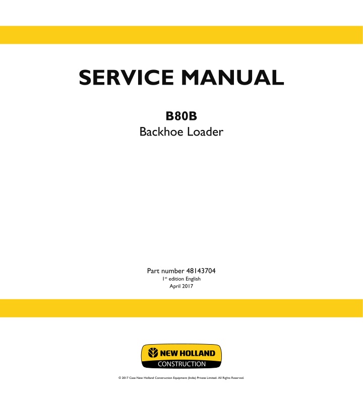
SERVICE MANUAL B80B Backhoe Loader Part number 48143704 1st edition English April 2017 CONSTRUCTION 2017 Case New Holland Construction Equipment (India) Private Limited. All Rights Reserved.
Contents INTRODUCTION Engine....................................................................................... 10 [10.001] Engine and crankcase ............................................................. 10.1 [10.254] Intake and exhaust manifolds and muffler ......................................... 10.2 [10.400] Engine cooling system ............................................................. 10.3 Transmission.............................................................................. 21 [21.100] Mechanical transmission lubrication system ....................................... 21.1 [21.112] Power shuttle transmission......................................................... 21.2 [21.134] Power shuttle transmission external controls ...................................... 21.3 [21.154] Power shuttle transmission internal components .................................. 21.4 [21.700] Torque converter ................................................................... 21.5 Front axle system ....................................................................... 25 [25.100] Powered front axle ................................................................. 25.1 [25.102] Front bevel gear set and differential ............................................... 25.2 [25.108] Final drive hub, steering knuckles, and shafts ..................................... 25.3 [25.400] Non-powered front axle ............................................................ 25.4 Rear axle system........................................................................ 27 [27.100] Powered rear axle.................................................................. 27.1 [27.106] Rear bevel gear set and differential................................................ 27.2 [27.124] Final drive hub, steering knuckles, and shafts ..................................... 27.3 Brakes and controls .................................................................... 33 [33.202] Hydraulic service brakes ........................................................... 33.1 [33.110] Parking brake or parking lock ...................................................... 33.2 Hydraulic systems....................................................................... 35 [35.000] Hydraulic systems.................................................................. 35.1 [35.300] Reservoir, cooler, and filters........................................................ 35.2 48143704 20/04/2017
[35.104] Fixed displacement pump.......................................................... 35.3 [35.359] Main control valve.................................................................. 35.4 [35.724] Front loader hydraulic system control.............................................. 35.5 [35.701] Front loader arm hydraulic system................................................. 35.6 [35.723] Front loader bucket hydraulic system.............................................. 35.7 [35.726] Excavator and backhoe hydraulic controls......................................... 35.8 [35.736] Boom hydraulic system ............................................................ 35.9 [35.737] Dipper hydraulic system.......................................................... 35.10 [35.738] Excavator and backhoe bucket hydraulic system................................ 35.11 [35.739] Swing arm hydraulic system ..................................................... 35.12 [35.AAA] Hydraulic systems generic sub-group........................................... 35.13 Frames and ballasting................................................................. 39 [39.129] Stabilizers .......................................................................... 39.1 Steering..................................................................................... 41 [41.101] Steering control .................................................................... 41.1 [41.200] Hydraulic control components...................................................... 41.2 [41.216] Cylinders ........................................................................... 41.3 Wheels...................................................................................... 44 [44.511] Front wheels........................................................................ 44.1 [44.520] Rear wheels........................................................................ 44.2 [44.AAA] Wheels generic sub-group ........................................................ 44.3 Cab climate control..................................................................... 50 [50.100] Heating............................................................................. 50.1 [50.200] Air conditioning..................................................................... 50.2 Electrical systems....................................................................... 55 [55.100] Harnesses and connectors......................................................... 55.1 [55.201] Engine starting system............................................................. 55.2 [55.301] Alternator........................................................................... 55.3 48143704 20/04/2017
https://www.ebooklibonline.com Hello dear friend! Thank you very much for reading. Enter the link into your browser. The full manual is available for immediate download. https://www.ebooklibonline.com
[55.518] Wiper and washer system.......................................................... 55.4 Front loader and bucket............................................................... 82 [82.100] Arm................................................................................. 82.1 [82.300] Bucket.............................................................................. 82.2 Booms, dippers, and buckets ....................................................... 84 [84.114] Boom pivoting support ............................................................. 84.1 [84.910] Boom............................................................................... 84.2 [84.912] Dipper arm ......................................................................... 84.3 Accessories ............................................................................... 88 [88.100] Accessories ........................................................................ 88.1 Platform, cab, bodywork, and decals............................................. 90 [90.150] Cab................................................................................. 90.1 [90.154] Cab doors and hatches ............................................................ 90.2 [90.156] Cab windshield and windows ...................................................... 90.3 [90.100] Engine hood and panels ........................................................... 90.4 48143704 20/04/2017
INTRODUCTION 48143704 20/04/2017 1
INTRODUCTION Safety rules Personal safety This is the safety alert symbol. It is used to alert you to potential personal injury hazards. Obey all safety messages that follow this symbol to avoid possible death or injury. Throughout this manual you will find the signal words DANGER, WARNING, and CAUTION followed by special in- structions. These precautions are intended for the personal safety of you and those working with you. Read and understand all the safety messages in this manual before you operate or service the machine. DANGER indicates a hazardous situation that, if not avoided, will result in death or serious injury. WARNING indicates a hazardous situation that, if not avoided, could result in death or serious injury. CAUTION indicates a hazardous situation that, if not avoided, could result in minor or moderate injury. FAILURE TO FOLLOW DANGER, WARNING, AND CAUTION MESSAGES COULD RESULT IN DEATH OR SERIOUS INJURY. Machine safety NOTICE: Notice indicates a situation that, if not avoided, could result in machine or property damage. Throughout this manual you will find the signal word Notice followed by special instructions to prevent machine or property damage. The word Notice is used to address practices not related to personal safety. Information NOTE: Note indicates additional information that clarifies steps, procedures, or other information in this manual. Throughout this manual you will find the word Note followed by additional information about a step, procedure, or other information in the manual. The word Note is not intended to address personal safety or property damage. 48143704 20/04/2017 3
INTRODUCTION Safety rules DANGER Improper operation or service of this machine can result in an accident. Do not operate this machine or perform any lubrication, maintenance, or repair on it until you have read and understood the operation, lubrication, maintenance, and repair information. Failure to comply will result in death or serious injury. D0010A WARNING Maintenance hazard! Always perform all service procedures punctually at the intervals stated in this manual. This ensures optimum performance levels and maximum safety during machine operation. Failure to comply could result in death or serious injury. W0132A NOTICE: Extreme working and environmental conditions require shortened service intervals. Use Case fluids, lubricants, and filters for the best protection and performance of your machine. All fluids, lubricants, and filters must be disposed of in compliance with environmental standards and regulations. Contact your Dealer with any questions regarding the service and maintenance of this machine. Use this manual with the operator's manual to understand and perform the complete service procedures. Read the safety decals and information decals on the machine. Read the Operator s Manual and safety manual. Understand the operation of the machine before you start any service. Before you service the machine, put a Do Not Operate tag on the steering wheel or over the key switch. Ensure the tag is at a location where everyone who might operate or service the machine may see clearly. Plastic and resin parts Avoid using gasoline, paint thinner, etc. when cleaning plastic parts, console, instrument cluster, etc. Use only water, mild soap, and a soft cloth when you clean these parts. Using gasoline, thinners, etc. can cause discoloration, cracking, or deformation of the part being cleaned. 48143704 20/04/2017 4
INTRODUCTION Safety rules - Ductile iron DANGER Altering cast ductile iron can cause it to weaken or break. Before you weld, cut, or drill holes on any part of this machine, make sure that the part is not cast ductile iron. Failure to comply will result in death or serious injury. D0148A Altering cast ductile iron can cause it to weaken or break. Unauthorized modifications to cast ductile iron parts can cause death or serious injury. Do not weld, cut, drill, repair, or attach items to cast ductile iron parts on this machine. Before you weld, cut, or drill holes on any part of this machine, make sure the part is not cast ductile iron. See your dealer if you do not know if a part is cast ductile iron. The following items are examples of cast ductile iron parts. There may also be other parts made of cast ductile iron that are not on the list below. two-wheel drive steering link dump links front axle stabilizers extend-a-hoe swing tower bucket linkage Air-Conditioning (A/C) compressor mounting bracket Do not make any unauthorized modifications. Consult an authorized dealer before making any changes, additions, or modifications to this machine. 48143704 20/04/2017 5
SERVICE MANUAL Engine B80B 48143704 20/04/2017 10
Engine - Engine and crankcase Engine - Remove Prior operation: Refer to Basic instructions Prior operation: Refer to Hood - Remove (90.100) Prior operation: Refer to Radiator - Remove (10.400) Prior operation: Refer to Exhaust manifold - Remove (10.254) NOTE: Put identification tags on all disconnected hoses and wires. Close all disconnected hoses and fittings with caps and plugs immediately. NOTE: The images in this procedure may be different from your machine and are for reference only. ATTENTION: Allow the engine to reach normal tempera- ture before performing any service or maintenance proce- dure. Wear safety gloves and goggles for protection from hot components and fluids or severe burns could result. 1. Drain engine oil by loosening the drain nut. Collect the oil in a clean container, cap it and keep it aside in a clean place. 2. Disconnect the fuel return and inlet lines (1) from the mud filter (4) and cap them immediately. Loosen the mounting bolts (2) and remove the assem- bly (3) from the machine. 1 PTIL13TLB0953AB 3. Remove the exhaust pipe (1) of the turbocharger and cap it. 2 PTIL13TLB0956AB 48143704 20/04/2017 10.1 [10.001] / 3
Engine - Engine and crankcase 4. Remove the muffler support bracket bolt (2). 3 PTIL13TLB0957AB 5. Remove the bolt (1) and the muffler assembly from the engine. 4 PTIL13TLB0958AB 6. Disconnect the throttle linkage (1) from the pump and set it aside. 5 PTIL13TLB0954AB 7. Disconnect the coolant temperature (1), alternator, oil pressure (2) and starter connectors from engine. Remove the starter. Refer to Engine starter - Remove (55.201). 6 PTIL13TLB0955AB 48143704 20/04/2017 10.1 [10.001] / 4
Engine - Engine and crankcase 8. Remove the access cover from the flywheel housing (1). Turn the flywheel for access to the cap screws. Remove the cap screws to disconnect the torque con- verter from the engine. Connect lifting equipment to the lifting eyes on the en- gine to hold the engine in place. 7 PTIL13TLB1470AA 9. Remove the bolts (1), flat washers, and nuts from the front engine mount. Loosen and remove the cap screws and flat washers that fasten the transmission to the engine. 8 PTIL13TLB0730AB Raise and remove the engine from the machine. NOTICE: Make sure that the flex plate/converter assembly stays in place on the transmission. If the engine will be separated from the transmission for an extended period of time fasten the flex plate/converter assembly in place on the transmission. 9 PTIL13TLB0729AA 48143704 20/04/2017 10.1 [10.001] / 5
Engine - Engine and crankcase Engine - Install If applicable, remove caps and plugs from previously disconnected hoses and fittings. Remove identification tags after making the hose and wire connections. NOTE: The photos in this procedure may be different from your machine and are for reference only. 1. Position the engine in the machine. NOTICE: Make sure that the flex plate/converter assembly stays in place on the transmission. 1 PTIL13TLB0729AA 2. Install and tighten the flat washers and cap screws se- curing the transmission to the engine. Tighten cap screws to a torque of 52 57 N m (38 42 lb ft). Install and tighten the front engine mounting bolts, flat washers, and nuts. Tighten the self-locking nuts to a torque of 90 100 N m (66 74 lb ft). 3. Disconnect the lifting equipment from the lifting eyes on the engine. 2 PTIL13TLB0730AA 4. Tighten the cap screws through the access in the fly- wheel housing (1) and fasten the flywheel to the flex plate. Tighten cap screws to a torque of 52 57 N m (38 42 lb ft) when fixing the torque converter. 5. Install the access cover to the bell housing. Tighten it to a torque value of 52 57 N m (38 42 lb ft). 6. Install the starter onto the engine. Tighten it to a torque value of 40 N m (29 lb ft). Refer to Engine starter - Install (55.201). 3 PTIL13TLB1470AA 48143704 20/04/2017 10.1 [10.001] / 6
Engine - Engine and crankcase 7. Connect the coolant temperature (1), alternator, oil pressure (2) connectors. 4 PTIL13TLB0955AB 8. Connect the fuel return and inlet lines (1) and mount the fuel filter assembly (3) by tightening the mounting bolts (2). 5 PTIL13TLB0953AB 9. Connect the throttle rod (1). 10. Connect the throttle cable from the mounting bracket. 11. Connect the electrical connector for the oil pressure switch. 6 PTIL13TLB0954AB 12. Install the exhaust pipe (1) of the turbocharger to the muffler end. Tighten it to a torque value of 6.5 7.5 N m (4.8 5.5 lb ft). 7 PTIL13TLB0956AB 48143704 20/04/2017 10.1 [10.001] / 7
Engine - Engine and crankcase 13. Attach the muffler and brackets (1) to the engine. Tighten it to a torque value of 32 38 N m (24 28 lb ft). 8 PTIL13TLB0958AB 14. Install the muffler support bracket bolt (2). Tighten it to a torque value of 32 38 N m (24 28 lb ft). 9 PTIL13TLB0957AB 15. Attach the aspiration hose and the crank case venti- lation hose. 16. Install the exhaust manifold. Refer to Exhaust mani- fold - Install (10.254). 17. Install the cooling pack. Refer to Radiator - Install (10.400). 18. Fill the engine oil and cooling system up to the pre- scribed level. 19. See capacities in Capacities for specifications. 20. Install air cleaner assembly. 10 PTIL13TLB1467AB 21. Install the hood. Refer to Hood - Install (90.100). 22. Connect the battery terminals. structions. Refer to Basic in- 23. Start the engine and keep it in idling. 24. Unlockthesupportstrutlockandlowertheloaderarm. 48143704 20/04/2017 10.1 [10.001] / 8
Engine - Engine and crankcase Engine - Troubleshooting NOTE: The following table lists problems and their possible causes with recommended remedial action. ATTENTION: When attending a repair the cause of the problem must also be investigated and corrected to avoid repeat failures. Problem Possible Cause Correction Engine does not develop full power Clogged air cleaner Clean or renew element Fuel line obstructed Faulty injectors Incorrect valve clearance adjustment Burnt, worn or sticking valves Clean Clean and reset Clean and reset Replace valves with new or oversize, and/or machine the valve guide bores Check head flatness and fit new gasket Check injectors and pump Renew piston rings or re-bore/re-sleeve as necessary Renew bulb Blown head gasket Incorrect fuel delivery Low cylinder compression Bulb burnt out Oil pressure warning light fails to operate Renew pressure switch Check and renew wiring Fit new gasket Clean Overall injection pump and injectors Check crankshaft bearings for damage, change as required. Drain and refill with specified oil and renew filter. cause of dilution Check oil level and top up as necessary. Overhaul or renew pump as necessary. Check oil filter is not clogged Overhaul pump or relief valve as necessary Replace thrust washer Install new bearing inserts and/or bearing clearance re-grind crankshaft Renew connecting rods Re-grind crankshaft and fit undersize bear- ing inserts Re-bore/re-sleeve block and fit i bore clear- ance new pistons Fit new pistons and rings Fit new rings, check bore and pistons for damage Fit new piston or pin Install new retainer, and check bore/pistons for damage Install new thrust plate Renew timing gear Check and adjust backlash /renew, timing gear Tighten hose connection, renew hose if damaged Renew radiator cap Repair/renew radiator Re-adjust fan belt Clean with compressed air Renew thermostat Check for source of leakage. Renew gas- ket or defective parts Overhaul water pump Warning Light pressure switch faulty Warning light circuit faulty Excessive exhaust smoke Exhaust leak on exhaust manifold Air cleaner dirty or restricted Excessive fuel delivery Engine knocks Diluted or thin oil Ascertain Insufficient oil supply Low oil pressure Excessive crankshaft end play Excessive connecting rod or main Bent or twisted connecting rods Crankshaft journals out of round Excessive piston to cylinder Excessive piston ring clearance Broken rings Excessive piston pin clearance Piston pin retainer loose or missing Excessive camshaft play Imperfections on timing gear teeth Excessive timing gear backlash Engine overheats Coolant hose connection leaking or col- lapsed Radiator cap defective or not sealing Radiator leakage Improper fan belt adjustment Radiator fins restricted Faulty thermostat Internal engine leakage Water pump faulty 48143704 20/04/2017 10.1 [10.001] / 9
Suggest: If the above button click is invalid. Please download this document first, and then click the above link to download the complete manual. Thank you so much for reading
Engine - Engine and crankcase Problem Possible Cause Correction Exhaust gas leakage into cooling Coolant aeration Renew cylinder head gasket Tighten all connections and check coolant level is correct. Ensure cylinder head gas- ket has not blown Renew cylinder head gasket installed Reverse flush entire clogged water Cylinder head gasket improperly installed Hot spot due to rust and scale or clogged water jackets Obstruction to radiator air flow Extended engine idling Oil cooler tube blocked Radiator core tubes blocked Faulty temperature sender Remove the obstruction Do not allow engine to idle for long periods Clean Check free flow Renew sender switch Water temperature gauge fails to reach normal operating temperature Renew thermostat Renew temperature gauge Top up, as necessary Drain and refill with correct grade of oil Clean pump screen Fit new relief valve Renew oil pump Overhaul pump Incorrect or faulty thermostat Faulty water temperature gauge Engine oil level low Wrong grade of oil Blocked oil pump sump screen Oil pressure relief valve faulty Oil pump worn Excessive oil pump rotor and shaft assem- bly clearance Excessive main or connecting rod bearing clearance Low oil pressure Install new bearings inserts and bearing clearance or re-grind crankshaft if neces- sary Reduce oil level Excessive oil consumption Engine oil level too high External oil leaks Renew gaskets and seals, where neces- sary. Check mating surfaces for damage or distortion Renew Renew gasket. Check head for damage or distortion Renewringsand/orre-bore/re-sleeveblock as necessary Repair/renew oil cooler assembly Worn valves, valve guides or bores Cylinder head gasket leaking Oil loss past the pistons and rings Oil cooler leak 48143704 20/04/2017 10.1 [10.001] / 10
https://www.ebooklibonline.com Hello dear friend! Thank you very much for reading. Enter the link into your browser. The full manual is available for immediate download. https://www.ebooklibonline.com