New Holland Boomer™ 40 Tier 4B (final) Compact Tractor Service Repair Manual Instant Download
New Holland Boomeru2122 40 Tier 4B (final) Compact Tractor Service Repair Manual Instant Download

Download Presentation

Please find below an Image/Link to download the presentation.
The content on the website is provided AS IS for your information and personal use only. It may not be sold, licensed, or shared on other websites without obtaining consent from the author. If you encounter any issues during the download, it is possible that the publisher has removed the file from their server.
You are allowed to download the files provided on this website for personal or commercial use, subject to the condition that they are used lawfully. All files are the property of their respective owners.
The content on the website is provided AS IS for your information and personal use only. It may not be sold, licensed, or shared on other websites without obtaining consent from the author.
E N D
Presentation Transcript
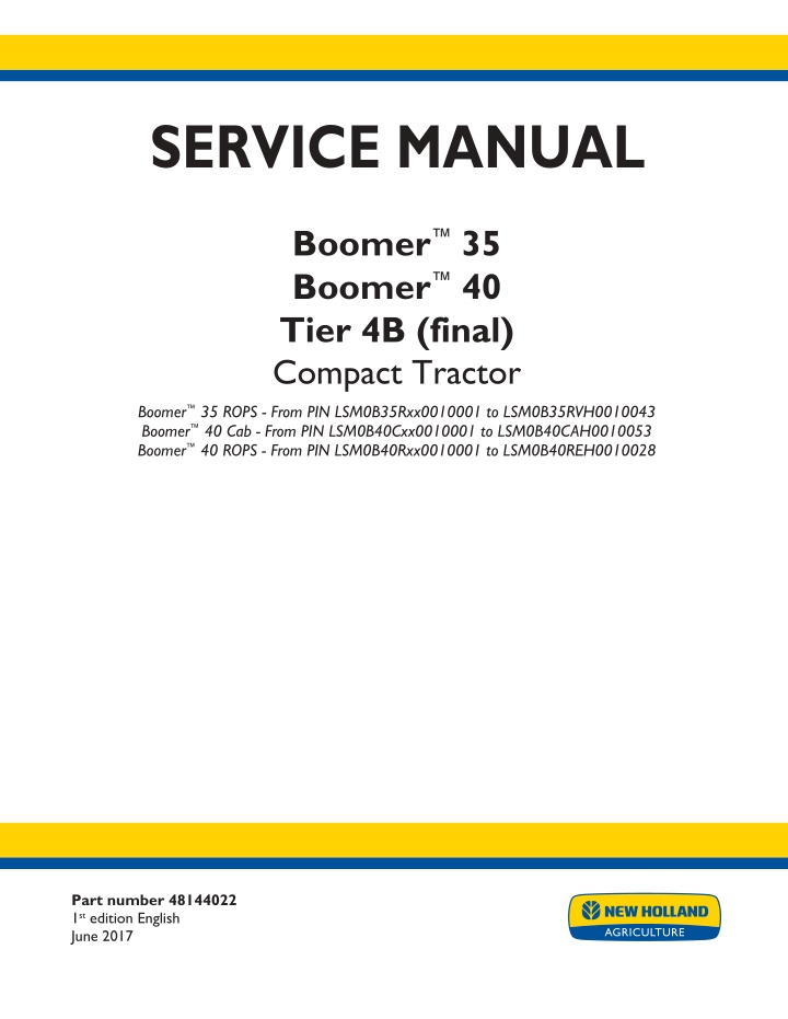
SERVICE MANUAL Boomer 35 Boomer 40 Tier 4B (final) Compact Tractor Boomer 35 ROPS - From PIN LSM0B35Rxx0010001 to LSM0B35RVH0010043 Boomer 40 Cab - From PIN LSM0B40Cxx0010001 to LSM0B40CAH0010053 Boomer 40 ROPS - From PIN LSM0B40Rxx0010001 to LSM0B40REH0010028 Part number 48144022 1st edition English June 2017 Printed in U.S.A. 2017 CNH Industrial America LLC. All Rights Reserved. New Holland is a trademark registered in the United States and many other countries, owned or licensed to CNH Industrial N.V., its subsidiaries or affiliates.
SERVICE MANUAL Boomer 35 Tier 4B (final), ROPS [LSM0B35Rxx0010001 - LSM0B35RVH0010043] Boomer 40 Tier 4B (final), Cab [LSM0B40Cxx0010001 - LSM0B40CAH0010053] Boomer 40 Tier 4B (final), ROPS [LSM0B40Rxx0010001 - LSM0B40REH0010028] 48144022 16/06/2017 EN
Link Product / Engine Product Market Product North America Engine Boomer 35 Tier 4B (final), ROPS [LSM0B35Rxx0010001 - LSM0B35RVH0010043] Boomer 40 Tier 4B (final), ROPS [LSM0B40Rxx0010001 - LSM0B40REH0010028] Boomer 40 Tier 4B (final), Cab [LSM0B40Cxx0010001 - LSM0B40CAH0010053] L3C19-T5 North America L3C19-T4 North America L3C19-T4 48144022 16/06/2017
https://www.ebooklibonline.com Hello dear friend! Thank you very much for reading. Enter the link into your browser. The full manual is available for immediate download. https://www.ebooklibonline.com
Contents INTRODUCTION Engine....................................................................................... 10 [10.001] Engine and crankcase ............................................................. 10.1 [10.216] Fuel tanks .......................................................................... 10.2 [10.206] Fuel filters .......................................................................... 10.3 [10.218] Fuel injection system............................................................... 10.4 [10.202] Air cleaners and lines .............................................................. 10.5 [10.254] Intake and exhaust manifolds and muffler ......................................... 10.6 [10.501] Exhaust Gas Recirculation (EGR) exhaust treatment.............................. 10.7 [10.400] Engine cooling system ............................................................. 10.8 [10.414] Fan and drive ...................................................................... 10.9 Clutch ....................................................................................... 18 [18.100] Clutch mechanical release control ................................................. 18.1 [18.110] Clutch and components ............................................................ 18.2 Power coupling........................................................................... 19 [19.110] Flywheel damper ................................................................... 19.1 Transmission.............................................................................. 21 [21.114] Mechanical transmission ........................................................... 21.1 [21.130] Mechanical transmission external controls......................................... 21.2 [21.140] Mechanical transmission internal components..................................... 21.3 [21.110] Master clutch housing .............................................................. 21.4 Four-Wheel Drive (4WD) system .................................................. 23 [23.314] Drive shaft.......................................................................... 23.1 [23.101] Mechanical control ................................................................. 23.2 Front axle system ....................................................................... 25 [25.100] Powered front axle ................................................................. 25.1 48144022 16/06/2017
[25.102] Front bevel gear set and differential ............................................... 25.2 [25.108] Final drive hub, steering knuckles, and shafts ..................................... 25.3 Rear axle system........................................................................ 27 [27.106] Rear bevel gear set and differential................................................ 27.1 [27.120] Planetary and final drives .......................................................... 27.2 Hydrostatic drive......................................................................... 29 [29.200] Mechanical control ................................................................. 29.1 [29.100] Transmission and steering hydrostatic control..................................... 29.2 [29.204] Reservoir, cooler, and lines ........................................................ 29.3 [29.218] Pump and motor components...................................................... 29.4 [29.202] Hydrostatic transmission ........................................................... 29.5 Power Take-Off (PTO)................................................................. 31 [31.101] Rear mechanical control ........................................................... 31.1 [31.104] Rear electro-hydraulic control...................................................... 31.2 [31.110] One-speed rear Power Take-Off (PTO) ............................................ 31.3 [31.120] Central Power Take-Off (PTO) ..................................................... 31.4 Brakes and controls .................................................................... 33 [33.110] Parking brake or parking lock ...................................................... 33.1 [33.120] Mechanical service brakes......................................................... 33.2 Hydraulic systems....................................................................... 35 [35.000] Hydraulic systems.................................................................. 35.1 [35.300] Reservoir, cooler, and filters........................................................ 35.2 [35.104] Fixed displacement pump.......................................................... 35.3 [35.350] Safety and main relief valves ...................................................... 35.4 [35.204] Remote control valves ............................................................. 35.5 [35.114] Three-point hitch control valve ..................................................... 35.6 [35.116] Three-point hitch cylinder .......................................................... 35.7 [35.724] Front loader hydraulic system control.............................................. 35.8 48144022 16/06/2017
Hitches, drawbars, and implement couplings.................................. 37 [37.100] Drawbars and towing hitches ...................................................... 37.1 [37.108] Rear three-point hitch external controls............................................ 37.2 [37.110] Rear three-point hitch .............................................................. 37.3 Steering..................................................................................... 41 [41.101] Steering control .................................................................... 41.1 [41.106] Tie rods............................................................................. 41.2 [41.200] Hydraulic control components...................................................... 41.3 [41.216] Cylinders ........................................................................... 41.4 [41.206] Pump............................................................................... 41.5 Wheels...................................................................................... 44 [44.511] Front wheels........................................................................ 44.1 [44.520] Rear wheels........................................................................ 44.2 Cab climate control..................................................................... 50 [50.100] Heating............................................................................. 50.1 [50.104] Ventilation .......................................................................... 50.2 [50.200] Air conditioning..................................................................... 50.3 [50.300] Cab pressurizing system........................................................... 50.4 [50.AAA] Cab climate control generic sub-group............................................ 50.5 Electrical systems....................................................................... 55 [55.000] Electrical system ................................................................... 55.1 [55.100] Harnesses and connectors......................................................... 55.2 [55.525] Cab engine controls................................................................ 55.3 [55.201] Engine starting system............................................................. 55.4 [55.301] Alternator........................................................................... 55.5 [55.640] Electronic modules................................................................. 55.6 [55.031] Parking brake electrical system.................................................... 55.7 [55.512] Cab controls........................................................................ 55.8 48144022 16/06/2017
[55.051] Cab Heating, Ventilation, and Air-Conditioning (HVAC) controls................... 55.9 [55.050] Heating, Ventilation, and Air-Conditioning (HVAC) control system............... 55.10 [55.023] Transmission position sensors and switches .................................... 55.11 [55.052] Central or middle Power Take-Off (PTO) control system ........................ 55.12 [55.610] Ground speed control ............................................................ 55.13 [55.DTC] FAULT CODES.................................................................. 55.14 Platform, cab, bodywork, and decals............................................. 90 [90.150] Cab................................................................................. 90.1 [90.110] Operator platform less cab ......................................................... 90.2 [90.114] Operator protections ............................................................... 90.3 [90.120] Mechanically-adjusted operator seat............................................... 90.4 [90.100] Engine hood and panels ........................................................... 90.5 [90.116] Fenders and guards................................................................ 90.6 48144022 16/06/2017
INTRODUCTION 48144022 16/06/2017 1
INTRODUCTION Foreword - Important notice regarding equipment servicing All repair and maintenance work listed in this manual must be carried out only by qualified dealership personnel, strictly complying with the instructions given, and using, whenever possible, the special tools. Anyone who performs repair and maintenance operations without complying with the procedures provided herein shall be responsible for any subsequent damages. The manufacturer and all the organizations of its distribution chain, including - without limitation - national, regional, or local dealers, reject any responsibility for damages caused by parts and/or components not approved by the manu- facturer, including those used for the servicing or repair of the product manufactured or marketed by the manufacturer. In any case, no warranty is given or attributed on the product manufactured or marketed by the manufacturer in case of damages caused by parts and/or components not approved by the manufacturer. The manufacturer reserves the right to make improvements in design and changes in specifications at any time without notice and without incurring any obligation to install them on units previously sold. Specifications, descriptions, and illustrative material herein are as accurate as known at time of publication but are subject to change without notice. In case of questions, refer to your NEW HOLLAND Sales and Service Networks. 48144022 16/06/2017 3
INTRODUCTION Safety rules Personal safety This is the safety alert symbol. It is used to alert you to potential personal injury hazards. Obey all safety messages that follow this symbol to avoid possible death or injury. Throughout this manual you will find the signal words DANGER, WARNING, and CAUTION followed by special in- structions. These precautions are intended for the personal safety of you and those working with you. Read and understand all the safety messages in this manual before you operate or service the machine. DANGER indicates a hazardous situation that, if not avoided, will result in death or serious injury. WARNING indicates a hazardous situation that, if not avoided, could result in death or serious injury. CAUTION indicates a hazardous situation that, if not avoided, could result in minor or moderate injury. FAILURE TO FOLLOW DANGER, WARNING, AND CAUTION MESSAGES COULD RESULT IN DEATH OR SERIOUS INJURY. Machine safety NOTICE: Notice indicates a situation that, if not avoided, could result in machine or property damage. Throughout this manual you will find the signal word Notice followed by special instructions to prevent machine or property damage. The word Notice is used to address practices not related to personal safety. Information NOTE: Note indicates additional information that clarifies steps, procedures, or other information in this manual. Throughout this manual you will find the word Note followed by additional information about a step, procedure, or other information in the manual. The word Note is not intended to address personal safety or property damage. 48144022 16/06/2017 5
INTRODUCTION Safety rules - Ecology and the environment Soil, air, and water quality is important for all industries and life in general. When legislation does not yet rule the treatment of some of the substances that advanced technology requires, sound judgment should govern the use and disposal of products of a chemical and petrochemical nature. Familiarize yourself with the relative legislation applicable to your country, and make sure that you understand this legislation. Where no legislation exists, obtain information from suppliers of oils, filters, batteries, fuels, anti-freeze, cleaning agents, etc., with regard to the effect of these substances on man and nature and how to safely store, use, and dispose of these substances. Helpful hints Avoid the use of cans or other inappropriate pressurized fuel delivery systems to fill tanks. Such delivery systems may cause considerable spillage. In general, avoid skin contact with all fuels, oils, acids, solvents, etc. Most of these products contain substances that may be harmful to your health. Modern oils contain additives. Do not burn contaminated fuels and or waste oils in ordinary heating systems. Avoid spillage when you drain fluids such as used engine coolant mixtures, engine oil, hydraulic fluid, brake fluid, etc. Do not mix drained brake fluids or fuels with lubricants. Store all drained fluids safely until you can dispose of the fluids in a proper way that complies with all local legislation and available resources. Do not allow coolant mixtures to get into the soil. Collect and dispose of coolant mixtures properly. The air-conditioning system contains gases that should not be released into the atmosphere. Consult an air-condi- tioning specialist or use a special extractor to recharge the system properly. Repair any leaks or defects in the engine cooling system or hydraulic system immediately. Do not increase the pressure in a pressurized circuit as this may lead to a component failure. Protect hoses during welding. Penetrating weld splatter may burn a hole or weaken hoses, allowing the loss of oils, coolant, etc. Battery recycling Batteries and electric accumulators contain several substances that can have a harmful effect on the environment if the batteries are not properly recycled after use. Improper disposal of batteries can contaminate the soil, groundwater, and waterways. NEW HOLLAND strongly recommends that you return all used batteries to a NEW HOLLAND dealer, who will dispose of the used batteries or recycle the used batteries properly. In some countries, this is a legal requirement. Mandatory battery recycling NOTE: The following requirements are mandatory in Brazil. Batteries are made of lead plates and a sulfuric acid solution. Because batteries contain heavy metals such as lead, CONAMA Resolution 401/2008 requires you to return all used batteries to the battery dealer when you replace any batteries. Do not dispose of batteries in your household garbage. Points of sale are obliged to: Accept the return of your used batteries Store the returned batteries in a suitable location Send the returned batteries to the battery manufacturer for recycling 48144022 16/06/2017 7
SERVICE MANUAL Engine Boomer 35 Tier 4B (final), ROPS [LSM0B35Rxx0010001 - LSM0B35RVH0010043] Boomer 40 Tier 4B (final), Cab [LSM0B40Cxx0010001 - LSM0B40CAH0010053] Boomer 40 Tier 4B (final), ROPS [LSM0B40Rxx0010001 - LSM0B40REH0010028] 48144022 16/06/2017 10
Engine - Engine and crankcase Engine - Remove Prior operation: Drain fluid Hydrostatic transmission - Change fluid (29.202) Prior operation: Drain fluid Mechanical transmission - Change fluid (21.114) Prior operation: Hood - Remove (90.100) Prior operation: Radiator - Remove (10.400) NOTE: Cap off all hydraulic and fuel fittings or tubes to prevent contamination. NOTE: Note the placement of cable ties for reassembly. 1. Remove the two M8 flange bolts (1) securing the rear cowling. 2. Remove the rear cowling (2). 1 NHIL16CT01367AA 3. Remove the four M10 bolts (2) that mount the hood support bracket (1) to the flywheel housing. 2 NHIL16CT01398AA 3 NHIL16CT01400AA 48144022 16/06/2017 10.1 [10.001] / 4
Engine - Engine and crankcase 4. Remove the M8 bolt (1) in the front of the Four Wheel Drive (FWD) guard tube. 5. Slide the guard tube rear-ward. 4 NHIL16CT01006AA 6. Use a roll pin punch and a hammer and drive the roll pin (1) through the coupler. 7. Slide the coupler rear-ward. 5 NHIL16CT00679AA Right-hand side 8. Remove the M6 bolt (1) and remove the ground wire (2) from the bell housing. 6 NHIL16CT01383AA 9. Loosen the hose clamps (1) and slide the suction tube coupler (2) rear-ward. 7 NHIL16CT00550AA 48144022 16/06/2017 10.1 [10.001] / 5
Engine - Engine and crankcase 10. Remove the banjo bolt (2) from the main hydraulic pump. 11. Remove the three M6 bolts (3) from the steering pump suction fitting (4). 12. Remove the suction tube (5). 13. Disconnect the main hydraulic pump outlet pipe (7). 14. For Roll Over Protective Structure (ROPS) tractor: 1. Disconnect the steering pump outlet hose (6). Cap off the hose and route the hose away from the engine. 8 NHIL16CT01377AA 15. For mechanical transmissions: 1. Remove the banjo bolt (8) from the Mid Mount Valve (MMV) pressure port. 2. Remove the main hydraulic pump outlet pipe (1) from the MMV. 16. For Hydro-Static Transmissions (HST): 1. Remove the main hydraulic pump outlet pipe (1) from the union fitting (2). 9 NHIL15CT00802AA Cab tractor only 17. Disconnect the steering pressure hose (2) at the back side of the resonator (1) . Cap off the hose and route the hose away from the engine. 10 NHIL17CT00216AA 48144022 16/06/2017 10.1 [10.001] / 6
Engine - Engine and crankcase 18. Disconnect the two heater coolant hoses (1)on the right side of the machine. 11 NHIL16CT01417AA 19. Disconnect the air conditioning lines at quick discon- nects (1)on the left side of the machine. 12 NHIL16CT01488AA Left-hand side 20. Removethecoatednutandremovetheshield(1)from the starter motor solenoid. 13 NHIL16CT01381AA 21. Remove the M8 flange nut and remove the power ca- ble (1) from the stud. 14 NHIL16CT01385AA 48144022 16/06/2017 10.1 [10.001] / 7
Suggest: If the above button click is invalid. Please download this document first, and then click the above link to download the complete manual. Thank you so much for reading
Engine - Engine and crankcase 22. Disconnect the Engine Control Unit (ECU) elec- trical connector (1) near the middle of the engine crankcase. 15 NHIL16CT01386AA 23. Disconnect the power and ground electrical connec- tors (1) above the starter motor. 16 NHIL16CT01387AA 24. Disconnectthefuelsupplyhose(1)fromthefuelwater separator filter to the fuel tank. 25. Disconnect the fuel return hose (2) from the high-pres- sure fuel pump to the right-hand fitting on the fuel cooler. 26. Disconnect the fuel return hose (3) from the fuel tank. 17 NHIL16CT01379AA 27. Disconnect the right-hand and left-hand steering hoses (1) at the power steering cylinders. 28. Tie hoses back out of the way toward rear of the trac- tor. 18 NHIL17CT00004AA 48144022 16/06/2017 10.1 [10.001] / 8
https://www.ebooklibonline.com Hello dear friend! Thank you very much for reading. Enter the link into your browser. The full manual is available for immediate download. https://www.ebooklibonline.com