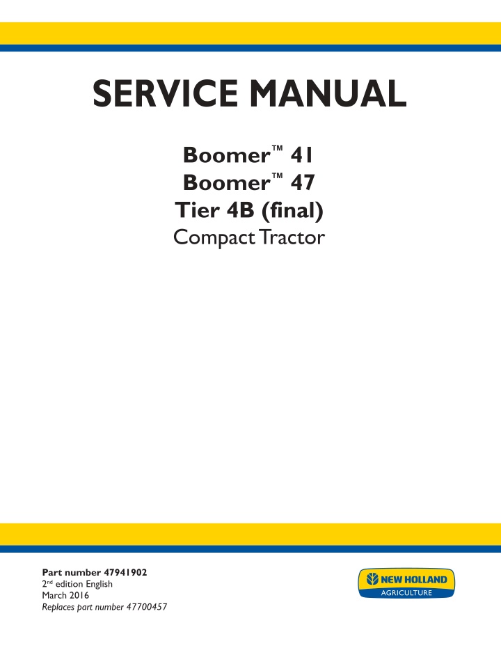
New Holland Boomer™ 47 Tier 4B (final) Compact Tractor Service Repair Manual Instant Download
New Holland Boomeru2122 47 Tier 4B (final) Compact Tractor Service Repair Manual Instant Download
Download Presentation

Please find below an Image/Link to download the presentation.
The content on the website is provided AS IS for your information and personal use only. It may not be sold, licensed, or shared on other websites without obtaining consent from the author. If you encounter any issues during the download, it is possible that the publisher has removed the file from their server.
You are allowed to download the files provided on this website for personal or commercial use, subject to the condition that they are used lawfully. All files are the property of their respective owners.
The content on the website is provided AS IS for your information and personal use only. It may not be sold, licensed, or shared on other websites without obtaining consent from the author.
E N D
Presentation Transcript
SERVICE MANUAL Boomer 41 Boomer 47 Tier 4B (final) Compact Tractor Part number 47941902 2nd edition English March 2016 Replaces part number 47700457 Printed in U.S.A. 2016 CNH Industrial America LLC. All Rights Reserved. New Holland is a trademark registered in the United States and many other countries, owned by or licensed to CNH Industrial N.V., its subsidiaries or affiliates.
SERVICE MANUAL Boomer 41 TIER 4B (FINAL), ROPS Boomer 41 TIER 4B (FINAL), Cab Boomer 47 TIER 4B (FINAL), ROPS Boomer 47 TIER 4B (FINAL), Cab 47941902 16/03/2016 EN
Link Product / Engine Product Market Product North America Engine N844L-F-30 Boomer 41 TIER 4B (FINAL), ROPS Boomer 41 TIER 4B (FINAL), Cab Boomer 47 TIER 4B (FINAL), ROPS Boomer 47 TIER 4B (FINAL), Cab North America N844L-F-30 North America N844L-F-34 North America N844L-F-34 47941902 16/03/2016
https://www.ebooklibonline.com Hello dear friend! Thank you very much for reading. Enter the link into your browser. The full manual is available for immediate download. https://www.ebooklibonline.com
Contents INTRODUCTION Engine....................................................................................... 10 [10.001] Engine and crankcase ............................................................. 10.1 [10.202] Air cleaners and lines .............................................................. 10.2 [10.206] Fuel filters .......................................................................... 10.3 [10.304] Engine lubrication system.......................................................... 10.4 [10.400] Engine cooling system ............................................................. 10.5 [10.501] Exhaust Gas Recirculation (EGR) exhaust treatment.............................. 10.6 Clutch ....................................................................................... 18 [18.100] Clutch mechanical release control ................................................. 18.1 [18.110] Clutch and components ............................................................ 18.2 [18.112] Slip clutch or flywheel damper ..................................................... 18.3 Transmission.............................................................................. 21 [21.114] Mechanical transmission ........................................................... 21.1 [21.140] Mechanical transmission internal components..................................... 21.2 Front axle system ....................................................................... 25 [25.100] Powered front axle ................................................................. 25.1 [25.102] Front bevel gear set and differential ............................................... 25.2 [25.108] Final drive hub, steering knuckles, and shafts ..................................... 25.3 [25.310] Final drives......................................................................... 25.4 Rear axle system........................................................................ 27 [27.106] Rear bevel gear set and differential................................................ 27.1 [27.120] Planetary and final drives .......................................................... 27.2 Hydrostatic drive......................................................................... 29 [29.100] Transmission and steering hydrostatic control..................................... 29.1 [29.202] Hydrostatic transmission ........................................................... 29.2 47941902 16/03/2016
[29.218] Pump and motor components...................................................... 29.3 Power Take-Off (PTO)................................................................. 31 [31.101] Rear mechanical control ........................................................... 31.1 [31.104] Rear electro-hydraulic control...................................................... 31.2 [31.110] One-speed rear Power Take-Off (PTO) ............................................ 31.3 [31.120] Central Power Take-Off (PTO) ..................................................... 31.4 Brakes and controls .................................................................... 33 [33.110] Parking brake or parking lock ...................................................... 33.1 [33.120] Mechanical service brakes......................................................... 33.2 Hydraulic systems....................................................................... 35 [35.000] Hydraulic systems.................................................................. 35.1 [35.104] Fixed displacement pump.......................................................... 35.2 [35.114] Three-point hitch control valve ..................................................... 35.3 [35.116] Three-point hitch cylinder .......................................................... 35.4 [35.204] Remote control valves ............................................................. 35.5 [35.300] Reservoir, cooler, and filters........................................................ 35.6 [35.350] Safety and main relief valves ...................................................... 35.7 [35.355] Hydraulic hand control ............................................................. 35.8 Hitches, drawbars, and implement couplings.................................. 37 [37.108] Rear three-point hitch external controls............................................ 37.1 [37.110] Rear three-point hitch .............................................................. 37.2 Steering..................................................................................... 41 [41.101] Steering control .................................................................... 41.1 [41.106] Tie rods............................................................................. 41.2 [41.200] Hydraulic control components...................................................... 41.3 [41.216] Cylinders ........................................................................... 41.4 Wheels...................................................................................... 44 47941902 16/03/2016
[44.511] Front wheels........................................................................ 44.1 [44.520] Rear wheels........................................................................ 44.2 Cab climate control..................................................................... 50 [50.100] Heating............................................................................. 50.1 [50.104] Ventilation .......................................................................... 50.2 [50.200] Air conditioning..................................................................... 50.3 Electrical systems....................................................................... 55 [55.000] Electrical system ................................................................... 55.1 [55.011] Fuel tank system ................................................................... 55.2 [55.031] Parking brake electrical system.................................................... 55.3 [55.048] Rear Power Take-Off (PTO) control system ....................................... 55.4 [55.100] Harnesses and connectors......................................................... 55.5 [55.201] Engine starting system............................................................. 55.6 [55.202] Cold start aid ....................................................................... 55.7 [55.302] Battery.............................................................................. 55.8 [55.404] External lighting .................................................................... 55.9 [55.405] External lighting switches and relays ............................................ 55.10 [55.408] Warning indicators, alarms, and instruments .................................... 55.11 [55.513] Cab transmission controls........................................................ 55.12 [55.525] Cab engine controls.............................................................. 55.13 [55.610] Ground speed control ............................................................ 55.14 [55.640] Electronic modules............................................................... 55.15 [55.989] Exhaust Gas Recirculation (EGR) electrical system ............................. 55.16 [55.DTC] FAULT CODES.................................................................. 55.17 Platform, cab, bodywork, and decals............................................. 90 [90.100] Engine hood and panels ........................................................... 90.1 [90.114] Operator protections ............................................................... 90.2 [90.116] Fenders and guards................................................................ 90.3 47941902 16/03/2016
[90.120] Mechanically-adjusted operator seat............................................... 90.4 [90.150] Cab................................................................................. 90.5 [90.151] Cab interior......................................................................... 90.6 [90.154] Cab doors and hatches ............................................................ 90.7 [90.156] Cab glazing ........................................................................ 90.8 47941902 16/03/2016
INTRODUCTION 47941902 16/03/2016 1
INTRODUCTION Foreword Boomer 41 Boomer 47 NA NA This repair manual provides the technical information needed to properly service the NEW HOLLAND models Boomer 41and 47 tractors. Use this manual in conjunction with the operator's manual for complete operation, adjustment, and maintenance information On NEW HOLLAND equipment, left and right are determined by standing behind the unit, looking in the direction of travel. NOTICE: Emissions sensors in the exhaust system and on the vehicle may be damaged by vibrations from use of impact wrenches or hammers during service work. Avoid using these tools when servicing components close to the sensors. Remove the sensors with care if use of these tools cannot be avoided. 47941902 16/03/2016 3
INTRODUCTION Safety rules Boomer 41 Boomer 47 NA NA Personal safety This is the safety alert symbol. It is used to alert you to potential personal injury hazards. Obey all safety messages that follow this symbol to avoid possible death or injury. Throughout this manual you will find the signal words DANGER, WARNING, and CAUTION followed by special in- structions. These precautions are intended for the personal safety of you and those working with you. Read and understand all the safety messages in this manual before you operate or service the machine. DANGER indicates a hazardous situation that, if not avoided, will result in death or serious injury. WARNING indicates a hazardous situation that, if not avoided, could result in death or serious injury. CAUTION indicates a hazardous situation that, if not avoided, could result in minor or moderate injury. FAILURE TO FOLLOW DANGER, WARNING, AND CAUTION MESSAGES COULD RESULT IN DEATH OR SERIOUS INJURY. Machine safety NOTICE: Notice indicates a situation that, if not avoided, could result in machine or property damage. Throughout this manual you will find the signal word Notice followed by special instructions to prevent machine or property damage. The word Notice is used to address practices not related to personal safety. Information NOTE: Note indicates additional information that clarifies steps, procedures, or other information in this manual. Throughout this manual you will find the word Note followed by additional information about a step, procedure, or other information in the manual. The word Note is not intended to address personal safety or property damage. 47941902 16/03/2016 4
SERVICE MANUAL Engine Boomer 41 TIER 4B (FINAL), ROPS Boomer 41 TIER 4B (FINAL), Cab Boomer 47 TIER 4B (FINAL), ROPS Boomer 47 TIER 4B (FINAL), Cab 47941902 16/03/2016 10
Engine - Engine and crankcase Engine - Remove NA NA Boomer 41 TIER 4B (FINAL), ROPS Boomer 47 TIER 4B (FINAL), ROPS 1. Chock all four wheels so that the tractor cannot move. 2. Disconnect negative (-) battery cable (1). 1 NHIL13CT01033AA 3. Disconnect headlight wire harness. 4. See Hood - Remove (90.100). 5. Disconnect the main and engine wire harnesses. 6. Turn off fuel supply at the filter (1), and then disconnect fuel hose. 2 93102239 7. Position a drain pan to collect drain oil and unfasten clamps (1). 8. Disassemble suction tube assembly (2). 3 93102240 47941902 16/03/2016 10.1 [10.001] / 3
Engine - Engine and crankcase 9. Remove the knobs (2) on both rear cover halves (1) and remove. 4 93102241 10. Remove the mat (1). 11. Remove the M8 nuts and bolts and remove cover (2). 5 93102242 12. Remove the bolts (2) and remove the pedals (1). 6 93102243 13. Remove the seven M8 and one M24 bolts (3). 14. Remove right-hand step (1) and left-hand step (2). 7 93102244 47941902 16/03/2016 10.1 [10.001] / 4
Engine - Engine and crankcase 15. Disconnect the front high pressure tube (1). 8 93102245 16. Disconnect steering hoses (2) and tubes (1). 9 93102246 17. Disconnect brake the rod (1), Hydrostatic Transmis- sion (HST) or gear transmission. 10 93102247 18. Disconnect brake rod (2) on the right-hand side and clutch rod on the left-hand side; gear transmission only. 11 93102248 (1) Clutch pedal 47941902 16/03/2016 10.1 [10.001] / 5
Engine - Engine and crankcase 1. Disassemble the brake rods linkage (1) and (2) as shown. 12 93102250 2. Remove bolts (2) securing the frame (1) to the fire wall, and remove frame. 13 93102251 3. Remove the fire wall (1) with the aid of a hoist. 14 93102252 4. Disconnect and remove the oil cooler (1) and related parts, as shown in figure 15. 15 93102253 47941902 16/03/2016 10.1 [10.001] / 6
Engine - Engine and crankcase Secure the tractor for separation: 1. Attach a chain sling (2) to the two hoist eyes on the engine: One located on the left-hand side above the exhaust manifold, the other on the right-hand side to the rear of the injector rail. 2. Attach a suitable hoist to the chain sling. 3. Roll a floor jack (1) under the tractor from the rear of the tractor, and place under the clutch housing. Raise the jack enough to support the drive train. 16 93105782 4. Remove eight M12 bolts (2) holding the engine (1) and transmission (3), while checking front wheel drive shaft for separation from the transmission. NOTE: The hoist and/or the floor jack may need to be raised or lowered to allow the separation of the engine from the clutch housing. 5. Carefullyrollthedrivetrainawayfromtheengine, using the floor jack for support. 17 93102254 18 93105783 47941902 16/03/2016 10.1 [10.001] / 7
Suggest: If the above button click is invalid. Please download this document first, and then click the above link to download the complete manual. Thank you so much for reading
Engine - Engine and crankcase Engine - Remove NA NA Boomer 41 TIER 4B (FINAL), Cab Boomer 47 TIER 4B (FINAL), Cab NOTICE: Prior to engine removal, the air conditioning system must be evacuated. ( See Air conditioning - Service instruction - Evacuating the Refrigerant (50.200), and the A/C lines must be disconnected. 1. Chock all four wheels so that the tractor cannot move. 2. Disconnect the negative (-) battery cable (1). 1 93102237 3. Disconnect the headlight wire harness. 4. See Hood - Remove (90.100). 5. Disconnect the main and engine wire harnesses. 6. Turn off fuel supply at the filter (1), and then disconnect fuel hose. 2 93102239 7. Position a drain pan to collect drain oil and unfasten clamps (1). 8. Disassemble the suction tube assembly (2). 3 93102240 47941902 16/03/2016 10.1 [10.001] / 8
https://www.ebooklibonline.com Hello dear friend! Thank you very much for reading. Enter the link into your browser. The full manual is available for immediate download. https://www.ebooklibonline.com

