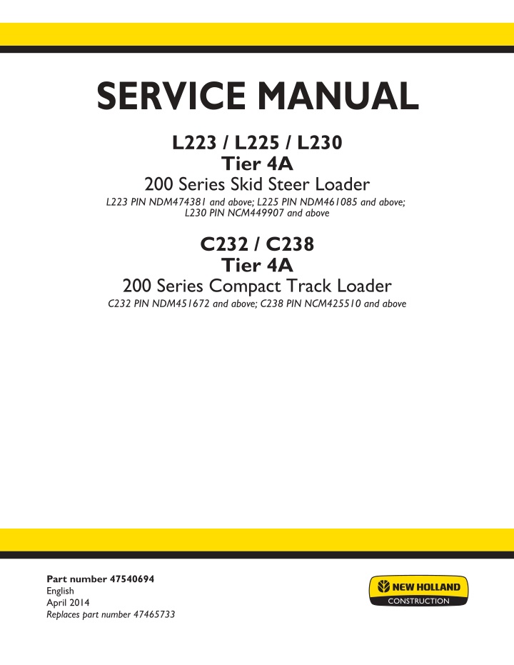
New Holland C238 TIER 4 Compact Track Loader Service Repair Manual Instant Download [NCM425510 - ]
New Holland C238 TIER 4 Compact Track Loader Service Repair Manual Instant Download [NCM425510 - ]
Download Presentation

Please find below an Image/Link to download the presentation.
The content on the website is provided AS IS for your information and personal use only. It may not be sold, licensed, or shared on other websites without obtaining consent from the author. If you encounter any issues during the download, it is possible that the publisher has removed the file from their server.
You are allowed to download the files provided on this website for personal or commercial use, subject to the condition that they are used lawfully. All files are the property of their respective owners.
The content on the website is provided AS IS for your information and personal use only. It may not be sold, licensed, or shared on other websites without obtaining consent from the author.
E N D
Presentation Transcript
SERVICE MANUAL L223 / L225 / L230 Tier 4A 200 Series Skid Steer Loader L223 PIN NDM474381 and above; L225 PIN NDM461085 and above; L230 PIN NCM449907 and above C232 / C238 Tier 4A 200 Series Compact Track Loader C232 PIN NDM451672 and above; C238 PIN NCM425510 and above Part number 47540694 English April 2014 Replaces part number 47465733 Printed in U.S.A. Copyright 2014 CNH Industrial America LLC. All Rights Reserved. New Holland is a registered trademark of CNH Industrial America LLC. Racine Wisconsin 53404 U.S.A.
Link Product / Engine Product Market Product North America North America North America North America North America Engine C232 TIER 4 [NDM451672 - ] C238 TIER 4 [NCM425510 - ] L223 TIER 4 [NDM474381 - ] L225 TIER 4 [NDM461085 - ] L230 TIER 4 [NCM449907 - ] F5HFL413H*A001 F5HFL413L*A001 F5HFL463A*F001 F5HFL413H*A001 F5HFL413L*A001 47540694 28/04/2014
Contents INTRODUCTION Engine....................................................................................... 10 [10.001] Engine and crankcase ............................................................. 10.1 [10.216] Fuel tanks .......................................................................... 10.2 [10.310] Aftercooler.......................................................................... 10.3 [10.400] Engine cooling system ............................................................. 10.4 [10.414] Fan and drive ...................................................................... 10.5 [10.501] Exhaust Gas Recirculation (EGR) - Diesel Particulate Filter (DPF) exhaust treatment .................................................................................... 10.6 Front axle system ....................................................................... 25 [25.450] Chain drive system................................................................. 25.1 Rear axle system........................................................................ 27 [27.650] Chain drive system ................................................................ 27.1 Hydrostatic drive......................................................................... 29 [29.202] Hydrostatic transmission ........................................................... 29.1 [29.134] Two-speed assembly............................................................... 29.2 [29.200] Mechanical control ................................................................. 29.3 [29.218] Pump and motor components...................................................... 29.4 Brakes and controls .................................................................... 33 [33.110] Parking brake or parking lock ...................................................... 33.1 Hydraulic systems....................................................................... 35 [35.000] Hydraulic systems.................................................................. 35.1 [35.104] Fixed displacement pump.......................................................... 35.2 [35.128] Auxiliary hydraulic function control................................................. 35.3 [35.300] Reservoir, cooler, and filters........................................................ 35.4 [35.350] Safety and main relief valves ...................................................... 35.5 47540694 28/04/2014
https://www.ebooklibonline.com Hello dear friend! Thank you very much for reading. Enter the link into your browser. The full manual is available for immediate download. https://www.ebooklibonline.com
[35.359] Main control valve.................................................................. 35.6 [35.600] High flow hydraulics................................................................ 35.7 [35.701] Front loader arm hydraulic system................................................. 35.8 [35.723] Front loader bucket hydraulic system.............................................. 35.9 [35.724] Front loader hydraulic system control............................................ 35.10 [35.734] Tool quick coupler hydraulic system ............................................. 35.11 Frames and ballasting................................................................. 39 [39.140] Ballasts and supports .............................................................. 39.1 Wheels...................................................................................... 44 [44.511] Front wheels........................................................................ 44.1 [44.520] Rear wheels........................................................................ 44.2 Tracks and track suspension........................................................ 48 [48.100] Tracks .............................................................................. 48.1 [48.130] Track frame and driving wheels.................................................... 48.2 [48.134] Track tension units ................................................................. 48.3 [48.138] Track rollers ........................................................................ 48.4 Cab climate control..................................................................... 50 [50.100] Heating............................................................................. 50.1 [50.200] Air conditioning..................................................................... 50.2 Electrical systems....................................................................... 55 [55.000] Electrical system ................................................................... 55.1 [55.010] Fuel injection system............................................................... 55.2 [55.011] Fuel tank system ................................................................... 55.3 [55.012] Engine cooling system ............................................................. 55.4 [55.014] Engine intake and exhaust system................................................. 55.5 [55.015] Engine control system.............................................................. 55.6 [55.019] Hydrostatic drive control system ................................................... 55.7 [55.031] Parking brake electrical system.................................................... 55.8 47540694 28/04/2014
[55.036] Hydraulic system control ........................................................... 55.9 [55.050] Heating, Ventilation, and Air-Conditioning (HVAC) control system............... 55.10 [55.100] Harnesses and connectors....................................................... 55.11 [55.302] Battery............................................................................ 55.12 [55.404] External lighting .................................................................. 55.13 [55.512] Cab controls...................................................................... 55.14 [55.525] Cab engine controls.............................................................. 55.15 [55.DTC] FAULT CODES.................................................................. 55.16 Front loader and bucket............................................................... 82 [82.100] Arm................................................................................. 82.1 [82.300] Bucket.............................................................................. 82.2 Platform, cab, bodywork, and decals............................................. 90 [90.154] Cab doors and hatches ............................................................ 90.1 47540694 28/04/2014
INTRODUCTION 47540694 28/04/2014 1
INTRODUCTION Foreword - Important notice regarding equipment servicing NA NA NA NA NA C232 C238 L223 TIER 4 [NDM474381 - ] L225 L230 All repair and maintenance work listed in this manual must be carried out only by qualified dealership personnel, strictly complying with the instructions given, and using, whenever possible, the special tools. Anyone who performs repair and maintenance operations without complying with the procedures provided herein shall be responsible for any subsequent damages. The manufacturer and all the organizations of its distribution chain, including - without limitation - national, regional, or local dealers, reject any responsibility for damages caused by parts and/or components not approved by the manu- facturer, including those used for the servicing or repair of the product manufactured or marketed by the manufacturer. In any case, no warranty is given or attributed on the product manufactured or marketed by the manufacturer in case of damages caused by parts and/or components not approved by the manufacturer. The information in this manual is up-to-date at the date of the publication. It is the policy of the manufacturer for continuous improvement. Some information could not be updated due to modifications of a technical or commercial type, or changes to the laws and regulations of different countries. In case of questions, refer to your NEW HOLLAND CONSTRUCTION Sales and Service Networks. 47540694 28/04/2014 3
INTRODUCTION Safety rules NA NA NA NA NA C232 C238 L223 TIER 4 [NDM474381 - ] L225 L230 Personal safety This is the safety alert symbol. It is used to alert you to potential personal injury hazards. Obey all safety messages that follow this symbol to avoid possible death or injury. Throughout this manual you will find the signal words DANGER, WARNING, and CAUTION followed by special in- structions. These precautions are intended for the personal safety of you and those working with you. Read and understand all the safety messages in this manual before you operate or service the machine. DANGER indicates a hazardous situation that, if not avoided, will result in death or serious injury. WARNING indicates a hazardous situation that, if not avoided, could result in death or serious injury. CAUTION indicates a hazardous situation that, if not avoided, could result in minor or moderate injury. FAILURE TO FOLLOW DANGER, WARNING, AND CAUTION MESSAGES COULD RESULT IN DEATH OR SERIOUS INJURY. Machine safety NOTICE: Notice indicates a situation that, if not avoided, could result in machine or property damage. Throughout this manual you will find the signal word Notice followed by special instructions to prevent machine or property damage. The word Notice is used to address practices not related to personal safety. Information NOTE: Note indicates additional information that clarifies steps, procedures, or other information in this manual. Throughout this manual you will find the word Note followed by additional information about a step, procedure, or other information in the manual. The word Note is not intended to address personal safety or property damage. 47540694 28/04/2014 4
INTRODUCTION Safety rules - Personal safety NA NA NA NA NA C232 C238 L223 L225 L230 Carefully study these precautions, and those included in the external attachment operators manual, and insist that they be followed by those working with and for you. 1. Thoroughly read and understand this manual and the attachment Operator s Manual before operating this or any other equipment. 2. Be sure all people and pets are clear of the machine before starting. Sound the horn, if equipped, three times before starting engine. 3. Only the operator should be on the machine when in operation. Never allow anyone to climb on to the machine while it is in motion. If the machine is equipped with an Instructors Seat, this must only be used for training purposes. Passengers must not be allowed to use the Instructors Seat. 4. Keep all shields in place. Never work around the machine or any of the attachments while wearing loose clothing that might catch on moving parts. 5. Observe the following precautions whenever lubricating the machine or making adjustments. Disengage all clutching levers or switches. Lower the attachment, if equipped, to the ground or raise the attachment completely and engage the cylinder safety locks. Completing these actions will prevent the attachment from lowering unexpectedly. Engage the parking brake. Shut off the engine and remove the key. Wait for all machine movement to stop before leaving the operators platform. 6. Always keep the machine in gear while travelling downhill. 7. The machine should always be equipped with sufficient front or rear axle weight for safe operation. 8. Under some field conditions, more weight may be required at the front or rear axle for adequate stability. This is especially important when operating in hilly conditions or/when using heavy attachments. 9. Always lower the attachment, shut off the engine, set the parking brake, engage the transmission gears, remove the key and wait for all machine movement to stop before leaving the operators platform. 10. If the attachment or machine should become obstructed or plugged; set the parking brake, shut off the engine and remove the key, engage the transmission gears, wait for all machine or attachment motion to come to a stop, before leaving the operators platform to removing the obstruction or plug. 11. Never disconnect or make any adjustments to the hydraulic system unless the machine and/or the attachment is lowered to the ground or the safety lock(s) is in the engaged position. 12. Use of the flashing lights is highly recommended when operating on a public road. 13. When transporting on a road or highway, use accessory lights and devices for adequate warning to the opera- tors of other vehicles. In this regard, check local government regulations. Various safety lights and devices are available from your NEW HOLLAND CONSTRUCTION dealer. 14. Practice safety 365 days a year. 15. Keep all your equipment in safe operating condition. 16. Keep all guards and safety devices in place. 17. Always set the parking brake, shut off the engine and remove the key, engage the transmission gears, wait for all machine or attachment motion to come to a stop, before leaving the operators platform to service the machine and attachment. 18. Remember: A careful operator is the best insurance against an accident. 19. Extreme care should be taken in keeping hands and clothing away from moving parts. 47540694 28/04/2014 5
SERVICE MANUAL Engine C232 TIER 4 [NDM451672 - ] C238 TIER 4 [NCM425510 - ] L223 TIER 4 [NDM474381 - ] L225 TIER 4 [NDM461085 - ] L230 TIER 4 [NCM449907 - ] 47540694 28/04/2014 10
Engine - Engine and crankcase Engine - Remove NA Mechanical hydraulic controls NA Mechanical hydraulic controls NA Mechanical hydraulic controls NA Mechanical hydraulic controls C232 TIER 4 [NDM451672 - ] C238 TIER 4 [NCM425510 - ] L225 TIER 4 [NDM461085 - ] L230 TIER 4 [NCM449907 - ] WARNING Avoid injury! Always do the following before lubricating, maintaining, or servicing the machine. 1. Disengage all drives. 2. Engage parking brake. 3. Lower all attachments to the ground, or raise and engage all safety locks. 4. Shut off engine. 5. Remove key from key switch. 6. Switch off battery key, if installed. 7. Wait for all machine movement to stop. Failure to comply could result in death or serious injury. W0047A WARNING Fire hazard! When handling diesel fuel, observe the following precautions: 1. Do not smoke. 2. Never fill the tank when the engine is running. 3. Wipe up spilled fuel immediately. Failure to comply could result in death or serious injury. W0099A WARNING Escaping fluid! Hydraulic fluid or diesel fuel leaking under pressure can penetrate the skin and cause infection or other injury. To prevent personal injury: Relieve all pressure before disconnecting fluid lines or per- forming work on the hydraulic system. Before applying pressure, make sure all connections are tight and all components are in good condition. Never use your hand to check for suspected leaks under pressure. Use a piece of cardboard or wood for this purpose. If injured by leaking fluid, see your doctor immediately. Failure to comply could result in death or serious injury. W0178A WARNING Heavy objects! Lift and handle all heavy components using lifting equipment with adequate capacity. Always support units or parts with suitable slings or hooks. Make sure the work area is clear of all bystanders. Failure to comply could result in death or serious injury. W0398A Prior operation: Tilt the ROPS. Prior operation: Disconnect the battery. See Battery - Disconnect (55.302). Prior operation: Drain the coolant. See Radiator - Drain fluid (10.400). Prior operation: Drain the engine oil. Prior operation: Remove the rear engine access door. See Engine inspection door - Remove (90.102). Prior operation: Evacuate the A/C system (if equipped). See Air conditioning - Evacuate (50.200). 47540694 28/04/2014 10.1 [10.001] / 3
Engine - Engine and crankcase 1. Remove engine oil pan access plate (1). 1 RAPH12SSL0233AA 2. Disconnect the remote engine oil filter line (1) from the engine oil pan. 2 RAPH12SSL0232AA 3. Disconnect the tail lights (3) and disconnect the tail light electricalharness(4)fromtheenginehood. Ifequipped with A/C, disconnect the A/C lines (1) from the con- denser. Disconnect the fan motor electrical connector (2). 3 RAPH12SSL0237AA 47540694 28/04/2014 10.1 [10.001] / 4
Engine - Engine and crankcase 4. Support the engine hood with a suitable lifting device. Disconnect the engine hood strut (1). 4 RAPH12SSL0236AA 5. Remove the mounting hardware (2), and remove the engine hood (1). 5 RAPH12SSL0236AA 6. Remove the fenders (1). 6 RAPH12SSL0235AA 47540694 28/04/2014 10.1 [10.001] / 5
Engine - Engine and crankcase 7. Remove the engine cover (1). 7 RAPH12SSL0234AA 8. Remove the air cooler. See Aftercooler - Remove (10.310). 9. Remove the radiator. (10.400). See Radiator - Remove 10. Remove the radiator fan (1). 8 RAPH12SSL0062AA 11. Disconnect the dipstick tube (1) from the cooling pack- age bracket assembly. 9 RAPH12SSL0276AA 47540694 28/04/2014 10.1 [10.001] / 6
Engine - Engine and crankcase 12. Disconnect the intake tube for the air cooler (1). 10 RAPH12SSL0265AA 13. Disconnect the lower radiator hose retainers (1) from the cooling package bracket assembly. 11 RAPH12SSL0060AA 14. Remove the hydraulic oil filter (1). 12 RAPH12SSL0227AA 47540694 28/04/2014 10.1 [10.001] / 7
Engine - Engine and crankcase 15. Unbolt and remove the cooling package bracket as- sembly (1). 13 RAPH12SSL0228AA 16. Disconnect the overflow hose (1) from the lower radi- ator hose. 14 RAPH12SSL0059AA 17. Remove the deaeration tank cap (1), and disconnect the overflow hose (2) and return hose (3). Remove the deaeration tank assembly (4). 15 RAPH12SSL0225AA 47540694 28/04/2014 10.1 [10.001] / 8
Suggest: If the above button click is invalid. Please download this document first, and then click the above link to download the complete manual. Thank you so much for reading
Engine - Engine and crankcase 18. Remove the U bolt (1) on the exhaust pipe. 16 RAPH12SSL0226AA 19. Disconnect the following sensors: Diesel particulate filter (DPF) inlet temperature sen- sor (exhaust gas temp sensor #2) (1) Diesel oxidation catalyst (DOC) inlet temperature sensor (exhaust gas temp sensor #1) (2) Heated exhaust gas oxygen sensor (lambda sen- sor) (4) DPF pressure sensor (5) 20. Remove the exhaust clamp (3). 17 RAPH12SSL0071AA 21. Support the DPF assembly (2) with a suitable lifting device. Remove the mounting bolts (1), and remove the DPF assembly (2). 18 RAPH12SSL0070AA 47540694 28/04/2014 10.1 [10.001] / 9
https://www.ebooklibonline.com Hello dear friend! Thank you very much for reading. Enter the link into your browser. The full manual is available for immediate download. https://www.ebooklibonline.com

