New Holland CX880 Combine Service Repair Manual Instant Download
New Holland CX880 Combine Service Repair Manual Instant Download

Download Presentation

Please find below an Image/Link to download the presentation.
The content on the website is provided AS IS for your information and personal use only. It may not be sold, licensed, or shared on other websites without obtaining consent from the author. If you encounter any issues during the download, it is possible that the publisher has removed the file from their server.
You are allowed to download the files provided on this website for personal or commercial use, subject to the condition that they are used lawfully. All files are the property of their respective owners.
The content on the website is provided AS IS for your information and personal use only. It may not be sold, licensed, or shared on other websites without obtaining consent from the author.
E N D
Presentation Transcript
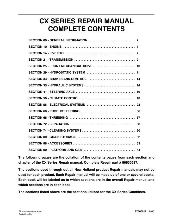
CX SERIES REPAIR MANUAL COMPLETE CONTENTS SECTION 00 - GENERAL INFORMATION . . . . . . . . . . . . . . . . . . . . . . . . . . . . . 2 SECTION 10 - ENGINE . . . . . . . . . . . . . . . . . . . . . . . . . . . . . . . . . . . . . . . . . . . . . . 3 SECTION 14 - LIVE PTO . . . . . . . . . . . . . . . . . . . . . . . . . . . . . . . . . . . . . . . . . . . . . 7 SECTION 21 - TRANSMISSION . . . . . . . . . . . . . . . . . . . . . . . . . . . . . . . . . . . . . . . 9 SECTION 25 - FRONT MECHANICAL DRIVE . . . . . . . . . . . . . . . . . . . . . . . . . . . 10 SECTION 29 - HYDROSTATIC SYSTEM . . . . . . . . . . . . . . . . . . . . . . . . . . . . . . . 11 SECTION 33 - BRAKES AND CONTROL . . . . . . . . . . . . . . . . . . . . . . . . . . . . . . 14 SECTION 35 - HYDRAULIC SYSTEMS . . . . . . . . . . . . . . . . . . . . . . . . . . . . . . . . 14 SECTION 41 - STEERING AXLE . . . . . . . . . . . . . . . . . . . . . . . . . . . . . . . . . . . . . . 16 SECTION 50 - CLIMATE CONTROL . . . . . . . . . . . . . . . . . . . . . . . . . . . . . . . . . . . 18 SECTION 55 - ELECTRICAL SYSTEMS . . . . . . . . . . . . . . . . . . . . . . . . . . . . . . . 23 SECTION 60 - PRODUCT FEEDING . . . . . . . . . . . . . . . . . . . . . . . . . . . . . . . . . . . 56 SECTION 66 - THRESHING . . . . . . . . . . . . . . . . . . . . . . . . . . . . . . . . . . . . . . . . . . 57 SECTION 72 - SEPARATION . . . . . . . . . . . . . . . . . . . . . . . . . . . . . . . . . . . . . . . . . 58 SECTION 74 - CLEANING SYSTEMS . . . . . . . . . . . . . . . . . . . . . . . . . . . . . . . . . . 60 SECTION 80 - GRAIN STORAGE . . . . . . . . . . . . . . . . . . . . . . . . . . . . . . . . . . . . . 62 SECTION 88 - ACCESSORIES . . . . . . . . . . . . . . . . . . . . . . . . . . . . . . . . . . . . . . . . 63 SECTION 90 - PLATFORM AND CAB . . . . . . . . . . . . . . . . . . . . . . . . . . . . . . . . . 64 The following pages are the collation of the contents pages from each section and chapter of the CX Series Repair manual. Complete Repair part # 86630597. The sections used through out all New Holland product Repair manuals may not be used for each product. Each Repair manual will be made up of one or several books. Each book will be labeled as to which sections are in the overall Repair manual and which sections are in each book. The sections listed above are the sections utilized for the CX Series Combines. 87360012 8/05 2005 CNH AMERICA LLC Printed In U.S.A.
SECTION 00 - - GENERAL INFORMATION SECTION 00 - - GENERAL INFORMATION CONTENTS Section Description Page Introduction Important information General instructions Shimming Rotating shaft seals O--ring seals Sealing compounds Cotter pins Spare parts Tools . . . . . . . . . . . . . . . . . . . . . . . . . . . . . . . . . . . . . . . . . . . . . . . . . . . . . . . . . . . . . . . . . . . . . . Safety regulations . . . . . . . . . . . . . . . . . . . . . . . . . . . . . . . . . . . . . . . . . . . . . . . . . . . . . . . . . . . . . Accident prevention . . . . . . . . . . . . . . . . . . . . . . . . . . . . . . . . . . . . . . . . . . . . . . . . . . . . . . . . . Safety rules . . . . . . . . . . . . . . . . . . . . . . . . . . . . . . . . . . . . . . . . . . . . . . . . . . . . . . . . . . . . . . . . General guidelines . . . . . . . . . . . . . . . . . . . . . . . . . . . . . . . . . . . . . . . . . . . . . . . . . . . . . . . Start-up . . . . . . . . . . . . . . . . . . . . . . . . . . . . . . . . . . . . . . . . . . . . . . . . . . . . . . . . . . . . . . . . Hydraulic systems . . . . . . . . . . . . . . . . . . . . . . . . . . . . . . . . . . . . . . . . . . . . . . . . . . . . . . . Wheels and Tyres . . . . . . . . . . . . . . . . . . . . . . . . . . . . . . . . . . . . . . . . . . . . . . . . . . . . . . . Removal and Re-fitting . . . . . . . . . . . . . . . . . . . . . . . . . . . . . . . . . . . . . . . . . . . . . . . . . . . Explanation of machine serial numbers . . . . . . . . . . . . . . . . . . . . . . . . . . . . . . . . . . . . . . . . . . . Units of measure -- Conversion chart . . . . . . . . . . . . . . . . . . . . . . . . . . . . . . . . . . . . . . . . . . . . . Minimum hardware tightening torques . . . . . . . . . . . . . . . . . . . . . . . . . . . . . . . . . . . . . . . . . . . . Drives . . . . . . . . . . . . . . . . . . . . . . . . . . . . . . . . . . . . . . . . . . . . . . . . . . . . . . . . . . . . . . . . . . . . . . . Main output shaft . . . . . . . . . . . . . . . . . . . . . . . . . . . . . . . . . . . . . . . . . . . . . . . . . . . . . . . . . . . Unloading output shaft . . . . . . . . . . . . . . . . . . . . . . . . . . . . . . . . . . . . . . . . . . . . . . . . . . . . . . . . . . . . . . . . . . . . . . . . . . . . . . . . . . . . . . . . . . . . . . . . . . . . . . . . . . . . . . . . . . . . . . . . . . . . . . . . . . . . . . . . . . . . . . . . . . . . . . . . . . . . . . . . . . . . . . . . . . . . . . . . . . . . . . . . . . . . . . . . . . . . . . . . . . . . . . . . . . . . . . . . . . . . . . . . . . . . . . . . . . . . . . . . . . . . . . . . . . . . . . . . . . . . . . . . . . . . . . . . . . . . . . . . . . . . . . . . . . . . . . . . . . . . . . . . . . . . . . . . . . . . . . . . . . . . . . . . . . . . . . . . . . . . . . . . . . . . . . . . . . . . . . . . . . . . . . . . . . . . . . . . . . . . . . . . . . . . . . . . . . . . . . . . . . . . . . . . . . . . . . . . . . . . . . . . . . . . . . . . . . . . . . . . . . . . . . . . . . . . . . . . . . . . . . . . . . . . . . . . . . . . . . . . . . . . . . . . . . . . . . . . . . . . . . . . . . . . . . . . . . . . . . . . . . . . . . . . . . . . . . . . . . . . . . . . . . . . . . . . . . . . . . . . . . . . . . . . . . . . . . . . . . . . . . . . . . . . . . . . . . . . . . . . . . . . . . . . . . . . 2 2 3 3 3 3 3 3 4 4 5 5 5 5 7 7 7 7 8 9 10 12 14 16 00-1
SECTION 00 - - GENERAL INFORMATION INTRODUCTION This manual is subdivided in sections marked by two-digit numbers, with independent page numbering within each section. For a quick reference, these sections have the same identification number and the same descrip- tion of the relevant Flat Time Rate Manual. The dealt matters and the information can be easily detected by index on the previous pages. At the bottom of each page there is the manual print number and the relevant publication/up-dating date. The pages of further up-datings shall have the same print number, followed by a two-digit number (for example: 1stUp-dating604.62.501.01; 2ndUp-dating604.62.501.02; etc.)andtherelevantpublicationdate.Thesepages shall be completed by the new print of the index, duly revised. The information of this manual are up-dated at the date of the publication. As NEW HOLLAND continuously im- provesitsproductrange,someinformation couldbenotup-datedduetomodifications oftechnicalorcommercial type, as well as for suiting the law regulations of the different countries. In case of disagreement, refer to NEW HOLLAND Sales and Service networks. IMPORTANT INFORMATION All repair and maintenance works listed in this manual must be carried out only by staff belonging to the NEW HOLLAND Service network, strictly complying with the instructions given and using, whenever required, the special tools. Anyone who carries out the above operations without complying with the prescriptions shall be responsible for the subsequent damages. The manufacturer and all the organizations of its distribution chain, including -- without limitation -- national, re- gional or local dealers, reject any responsibility for damages due to the anomalous behaviour of parts and/or components not approved by the manufacturer himself, including those used for the servicing or repair of the product manufactures or marketed by the Manufacturer. In any case, no warranty is given or attributed on the product manufactures of marketed by the Manufacturer in case of damages due to an anomalous behaviour of parts and/or components not approved by the Manufac- turer. No reproduction, though partial of text and illustrations allowed 00-2
https://www.ebooklibonline.com Hello dear friend! Thank you very much for reading. Enter the link into your browser. The full manual is available for immediate download. https://www.ebooklibonline.com
SECTION 00 - - GENERAL INFORMATION GENERAL INSTRUCTIONS SHIMMING O- -RING SEALS For each adjustment operation, select adjusting shims and measure individually using a micrometer, then add up the recorder values. Do not rely on measuring the entire shimming set, which may be in- correct, orthe rated valueindicated for each onshim. Lubricate the O--RING seals before inserting them in the seats, this willprevent them from overturning and twisting, which would jeopardise sealing efficiency. ROTATING SHAFT SEALS SEALING COMPOUNDS For correct rotating shaft sealinstallation, proceedas follows: -- before assembly, allow the seal to soak in the oil it will be sealing for at least thirty minutes Apply one of the following sealing compounds on the mating surfaces marked with an X: RTV SILMATE, RHODORSIL CAF 1 GASKET. Before applying the sealing compound, prepare the surfaces as follows: -- thoroughly clean the shaft and check that the working surface on the shaft is not damaged or LOCTITE PLASTIC -- position the sealing lip facing the fluid; with hydrodynamic lips, take into consideration the shaft rotation direction and position the grooves sothat they willdeviatethe fluidtowards theinner side of the seal -- remove any incrustations using a metal brush; -- thoroughly de--grease the surfaces using one of the following cleaning agents: trichlorethylene, petrol or a water and soda solution. -- coat the sealing lip with a thin layer of lubricant (use oil rather than grease) and fill the gap between the sealing lip and the dust lip ondouble lip seals with grease -- insert the seal in its seat and press down using a flat punch, do not tap the seal with a hammer or mallet COTTER PINS -- whilst inserting the seal, check that it is perpendicular to the seat; once settled, make surethatitmakescontactwiththethrustelement, if required Whenfitting splitcotter pins,ensurethatthe pinnotch is positioned in the direction of the force required to stress the pin. Spiral cotter pins do not require special positioning. -- to prevent damaging the seal lip on the shaft, position a protective guard during installation operations 00-3
SECTION 00 - - GENERAL INFORMATION PROTECTING THE ELECTRONIC/ ELECTRICAL SYSTEMS DURING CHARGING OR WELDING Never allow welding cables to lay on, near or across any electrical wiring or electronic component while welding is in progress. IMPORTANT: If welding must be performed on the unit, either the combine or the header (if it is attached), the battery ground cable must be disconnected from the electronic monitoring system and charging system will be damaged if this is not done. Toavoiddamage to the electronic/electrical systems, always observe the following: combine battery. The 1. Never make or break any of the charging circuit connections, including the battery connections, when the engine is running. Remove Reconnect completed. the the battery cable when ground cable. welding is 2. Never short any of the charging components to ground. 4. Always disconnect the negative cable from the battery when charging the battery in the combine with a battery charger. 3. Always disconnect the ground cable from the battery before arc welding on the combine or on any header attached to the combine. WARNING Batteries contain sulfuric acid. In case of contact with skin, flush the affected area with water for five minutes. Seek immediately. Avoid contact with the skin, eyesor clothing. Weareyeprotection when working near batteries. Position the welder ground clamp as close to the welding area as possible. medical attention If welding in close proximity to a computer module, then the module should be removed from the combine. 00-4
SECTION 10 - - ENGINE - - CHAPTER 1 SECTION 10 - - ENGINE Chapter 1 - - 7.5L New Holland Engine CONTENTS Section 10 000 Description Specifications Tightening Torques Special Tools Greases and Sealants Fault Finding Description and Operation Engine Overhaul--Introduction Injection Pump Timing Check Engine Disassembly and Overhaul:-- Cylinder Head, Valves and Related parts Front Cover and Timing Gears Oil Pan . . . . . . . . . . . . . . . . . . . . . . . . . . . . . . . . . . . . . . . . . . . . . . . . . . . . . . . . . . . . . . . . . . . . . Flywheel . . . . . . . . . . . . . . . . . . . . . . . . . . . . . . . . . . . . . . . . . . . . . . . . . . . . . . . . . . . . . . . . . . . . Rear cover plate . . . . . . . . . . . . . . . . . . . . . . . . . . . . . . . . . . . . . . . . . . . . . . . . . . . . . . . . . . . . . Oil pump . . . . . . . . . . . . . . . . . . . . . . . . . . . . . . . . . . . . . . . . . . . . . . . . . . . . . . . . . . . . . . . . . . . . Oil Pressure Relief Valve . . . . . . . . . . . . . . . . . . . . . . . . . . . . . . . . . . . . . . . . . . . . . . . . . . . . . . Camshaft, tappets and camshaft bearings . . . . . . . . . . . . . . . . . . . . . . . . . . . . . . . . . . . . . . . Pistons and Cylinder Block . . . . . . . . . . . . . . . . . . . . . . . . . . . . . . . . . . . . . . . . . . . . . . . . . . . . Crankshaft . . . . . . . . . . . . . . . . . . . . . . . . . . . . . . . . . . . . . . . . . . . . . . . . . . . . . . . . . . . . . . . . . . Engine compression test . . . . . . . . . . . . . . . . . . . . . . . . . . . . . . . . . . . . . . . . . . . . . . . . . . . . . . Page . . . . . . . . . . . . . . . . . . . . . . . . . . . . . . . . . . . . . . . . . . . . . . . . . . . . . . . . . . . . . . . . . . . . . . . . . . . . . . . . . . . . . . . . . . . . . . . . . . . . . . . . . . . . . . . . . . . . . . . . . . . . . . . . . . . . . . . . . . . . . . . . . . . . . . . . . . . . . . . . . . . . . . . . . . . . . . . . . . . . . . . . . . . . . . . . . . . . . . . . . . . . . . . . . . . . . . . . . . . . . . . . . . . . . . . . . . . . . . . . . . . . . . . . . . . . . . . . . . . . . . . . . . . . . . . . . . . . . . . . . . . . . . . . . . . . . . . . . . . . . . . . . . . . . . . . . . . . . . . . . . . . . . . . . . . . . . . . . . . . . . . . . . . . . . . . . . . . . . . . . . . . . . . . . . . . . . . . . . . . . . . . . . . . . . . . . . . . . . . . . . . . . . . . . . . . . . . . . . . . . . . . . . . . . . . . . . . . . . . . . . . . . . . . . . . . . . . . . . . . 2 10 11 12 13 17 23 24 10 001 10 100 10 101 10 106 10 102 10 103 10 102 10 102 10 102 10 106 10 105 10 103 10 001 . . . . . . . . . . . . . . . . . . . . . . . . . . . . . . . . . . . . . . . . . . . . . . . . . . . . . . . . . . . . . . . . . . . . . . . . . . . . . . . . . . . . . . . . . 27 38 42 43 44 45 47 48 51 60 69 10-1
SECTION 10 - - ENGINE - - CHAPTER 1 DESCRIPTION AND OPERATION 2 CYLINDER BLOCK ASSEMBLY The cylinder block is an alloy cast iron with deep cylinder skirts, and water jackets for cooling the cylinders. The cylinder bores are machined integral with the cylinder block, during the manufacturing process. Cylinders are in line and vertical and numbered 1 to 6 from the front to the rear of the engine. They canbe bored oversize for the fitment of sleeves, which are available in service. The oil pan is the reservoir for the engine oil lubrication system and a cast iron front cover on the front of the engine covers the timing gear assembly. The New Holland 7.5 Litre engine is a 6-cylinder turbocharged and aftercooled, having abore of 111.8 mm (4.4 ) and a stroke of 127 mm (5.0 ) which generates a displacement of 7.5L (456 in3). The engine uses a mechanical or electronically controlled in line injection pump depending on model and has been designed to meet current emission regulations and must only be serviced by an authorised service agent. For a detailed Description and Operation of the fuel system reference must be made to the Fuel System Chapter in this Section of the manual. Allenginesfeature crossflow cylinderheads, withthe inlet and exhaust manifolds on opposite sides of the cylinder head. The fuel and air combustion process, takes place in the specially designed bowl in the crown of the pistons. 10-17
SECTION 10 - - ENGINE - - CHAPTER 1 CYLINDER HEAD ASSEMBLY The cylinder head incorporates an inlet and exhaust valve per cylinder with the valve rocker arm shaft assembly bolted to the cylinder block through the cylinder head. Cylinder head retaining bolts are evenly spaced with a six point pattern around each cylinder, this ensures an even clamping load across the cylinder head area. The intake and exhaust manifolds are bolted to the head, the intake manifold is mounted on the right hand side of the engine, with the diesel injectors mounted outside the rocker cover. The exhaust manifold is mounted on the left hand side of the engine. Water outlet connections and thermostats being attached to the front of the cylinder block. Valve guides are integral in the cylinder head, and valves with oversize stems are available in service. Special replaceable sintered iron valve seats are pressed into each valve port during manufacture and oversize valve seats also available in service. All valves are fitted with positive valve rotators and valvestemoilseals.Valveclearanceismaintainedby adjustment of the self locking adjusting screw, mounted in each of the rocker arms. CAMSHAFT ASSEMBLY The camshaft runs in 5 replaceable bearings. The camshaft drive gear is in mesh with and driven bythe camshaft idler gear which is driven by the crankshaft timing gear. Camshaft end thrust is controlled by a thrust plate bolted to the block, and located between the camshaft gear and the front camshaft journal. A helicalgearismounted onthe rearof the camshaft, and drives the engine oil lubrication pump mounted forward of the flywheel. 3 396--E--16 T I 4 CRANKSHAFT ASSEMBLY The crankshaft is supported in the cylinder block by 7 main bearings. The crankshaft is manufactured from steel with machined finished crank webs End thrust is controlled incorporated in the centre main bearing of the crankshaft. An external damper is fitted to the crankshaft pulley to ensure smooth running operation. Front and rear crankshaft oil sealing is effected by cassette type seals that are designed for long and durable service life. by a thrust bearing 5 10-18
SECTION 10 - - ENGINE - - CHAPTER 1 CONNECTING RODS Connecting rods Teepee (wedge) shaped at the small end have been designed to reduce the reciprocating weight at connecting rods are of a heavy beam construction and are assembled as a matched set to eachengine. They are retained in position by the connecting rod big end cap and secured by two bolts per rod. The small end of the connecting rod is fitted with a replaceable bronze bushing, through which the free floating piston pin is fitted. The steel pin being held in place within the piston by two snap rings. the piston end. The 6 PISTONS Pistons are constructed of an aluminium silicon alloy with an iron insert for the top ring. The combustion chamber being recessed into the piston crowns. Each piston has two compression rings and one oil control ring, to reduce friction and increase positive sealing. All rings are located above the piston pin. A Engines with Electronically Controlled Injection Pump B Engines with Mechanically Controlled Injection Pump 7 MANIFOLDS Thecrossflow designaluminium intake,andcastiron exhaust manifolds, are on opposite sides of the cylinder head. This is designed to maintain balanced heat distribution within the cylinder head. The configuration of the manifolds also ensuresminimum heat transfer to the intake manifold. A grid heater is fitted to the intake manifold to assist in cold starting of the engine when coolant water temperature is below 30 C. 8 TIMING GEARS The crankshaft timing gear is heated and press fitted on to the front of the crankshaft, to a high degree of accuracyduringmanufacturing. This enablesprecise timing being maintained during the life of the engine. The crankshaft gear, 2, drives the idler gear, 3, which is attached to the front of the cylinder block. The idler gear then drives the camshaft gear, 1, and the injection pump gear, 4. The camshaft gear is bolted to the front of the camshaft, and is keyed to maintain position of the gear on the camshaft. 4 1 . .. . . 2 3 P396--E--36 9 10-19
SECTION 10 - - ENGINE - - CHAPTER 1 LUBRICATION SYSTEM 10 Engine Lubrication System Lubrication of the engine, Fig. 10, is maintained by arotortypeoilpumpmountedintherearof theengine block, forward of the flywheel on the left hand side of the engine. TA6010058 11 The oil pump is driven from the rear of the camshaft and draws oil from the engine oil pan through a tube and screen assembly. 12 10-20
SECTION 10 - - ENGINE - - CHAPTER 1 Aspringloadedrelief valveisintegralwith thedummy oil filter head mounted on the left hand side of the engine block and prevents over pressurisation of the system. 3 396--E--18 TI 13 The spin on type oil filter is mounted at the rear of the engine. 14 Oil flows from the filter to the main oil gallery, which runs the length of the cylinder block and also intersects the camshaft follower chamber. The main gallery supplies oil to the crankshaft main bearings, connecting rods and both big and small ends. The underside of the pistons and pins, are lubricated by oil pressure jets mounted adjacent to each main journal housing. The camshaft drive gear bushing is pressure lubricated through a drilled passage from the front main bearing. The gear has small oil passages machined on both sides allowing excess oil to escape. 396--E--26 TI 15 An intermittent flow of oil is directed to the valve rockerarmshaftassembly viaadrilledpassageinthe cylinder block. This is located vertically above No.1 camshaft bearing, 1, and aligns to a hole in the cylinder head. The rotation of the camshaft allows a controlled intermediate flow of lubrication. 1 396--E--16 T I 16 10-21
SECTION 10 - - ENGINE - - CHAPTER 1 Timing gears are lubricated by splashed oil from the cam follower chamber, and the pressure lubricated camshaft drive gear bushing. P396--E--36 17 The turbocharger is supplied with oil from the oil filter support housing, 1, mounted on the left hand side of the engine. 18 The fuel injection pump is pressure lubricated from a port, 1, on the right hand side of the engine block. The fuelpump is either electronically controlled using an electronic control unit 19 or Mechanically controlled depending on model build 20 10-22
SECTION 10 - - ENGINE - - CHAPTER 1 ENGINE OVERHAUL- -INTRODUCTION In the following procedures and illustrations the engine is shown removed from the vehicle however there are certain operations that can be performed with the engine installed. For concerns relating to the fuel system refer to the fuel system Chapter inthis manual. On enginesfitted with the electronically controlled fuel injection pump refer to the Engine Fault Codes chapter in the electrical section of the manual. Where it is necessary to remove the engine use a suitable hoist or overhead gantry and standard engineering procedures. Removal of the engine is described in Chapter 3 of Section 10 of this manual. Operations or repairs that can be performed with the engine still in the vehicle. 1. Front timing cover, Pump drive gear and idler gear. Removal of engine is required in order to remove and replace the camshaft timing gear. 2. Front pulley and damper assembly. 3. Cylinder head and associated inlet and exhaust components. 4. Fuel injection pump removal and timing. 5. Water pump, thermostat, components . 6. Oil pump relief valve. 7. Turbocharger. Dismantle techniques and by referring to the appropriate overhaul sections of this chapter. Always refer to the specification section as necessary. the engine following conventional NOTE: Where it is necessary to remove additional itemstogainaccesstothecomponentsontheengine Refer to Chapter 3 Remove and Replace, 7.5L NH Engine . and associated NOTE: All gaskets, seals, and O rings must be replaced during re-assembly. Where new sealant is to be applied refer to Engine Specifications . 10-23
SECTION 10 - - ENGINE - - CHAPTER 1 INJECTION PUMP TIMING CHECK If a fuel related concern is identified check the injection pump timing before proceeding with any other disassembly. NOTE: Where it is necessary to remove additional itemstogainaccesstothecomponentsontheengine Refer to Chapter 3 Replacement . 1. Remove engine drive belts. Engine Removal and 21 1. Remove injection pump timing cover. 22 2. Using 29mm socket (1--1/8 inch) socket rotate crankshaft to top dead centre (TDC) with number 1 cylinder firing. 0 23 3. When engine is at TDC the threaded hole in the injection pump drive flange aligns with the pump timing plate. 24 10-24
SECTION 10 - - ENGINE - - CHAPTER 1 4. To ensure the crankshaft is accurately positioned at TDC remove the crankshaft timing plug, 1, from the side of the engine block. IMPORTANT: DO NOT disturb the timing pin bush, 2. This has been accurately set during original manufacture. If the bush is moved then pump timing CAN NOT be accurately set. 25 5. insert the crankshaft timing pin 297672 into the side of the block. 26 6. If necessary gently turn the crankshaft to engage the rounded end of the timing pin in the slot of the crankshaft. This is not visible and must be performed by feel . 27 7. When the timing pin is located in the slot of the crankshaft the pin is fully seated. Do Not attempt to rotate the crankshaft when timing pin is fully inserted as damage will occur. 28 10-25
SECTION 10 - - ENGINE - - CHAPTER 1 8. Checkthattheinjection pumpgo/no-go timingpin ToolNo295005(NA-FNH00536-2)willscrewinto the pump hub. IMPORTANT: The engine must never be rotated while the timing pin is installed. 9. If the pin engages inthe pump timing plate (inset, Figure 30) when the crankshaft is at TDC the pump timing is correct. 29 10. If pump timing is incorrect and timing pin can not bescrewedintopump, removepump timinggear, install rigid timing pin 295005 (NA-FNH00536-1) into pump and refit timing gear. 30 NOTE: This injection pump timing check assumes that the crankshaft and camshaft timing gears were correctly positioned during engine assembly. To check the position of these timing gears it is necessary to remove the engine front cover. 10-26
Suggest: If the above button click is invalid. Please download this document first, and then click the above link to download the complete manual. Thank you so much for reading
SECTION 10 - - ENGINE - - CHAPTER 1 OVERHAUL 2 Op. 10 101 CYLINDER HEAD, VALVES, AND RELATED PARTS Cylinder Head Removal NOTE: The cylinder head can be removed with the engine installed in the combine. 1. Drain the engine coolant by placing a suitable container,1, below the coolant drain hose, 2. 2. Drain the coolant from the engine block using drain tap, 1, on left hand side of the radiator, 2. 1 10013105 31 2 1 10013106 32 3. Remove components in order to gain access to the cylinder head. Refer to Chapter 3 Remove and Replace, 7.5L NH Engine for further details. all necessary hardware and 33 4. Remove the fan belt. 34 10-27
https://www.ebooklibonline.com Hello dear friend! Thank you very much for reading. Enter the link into your browser. The full manual is available for immediate download. https://www.ebooklibonline.com