New Holland D180 Tier 3 Crawler Dozer Service Repair Manual Instant Download 1
New Holland D180 Tier 3 Crawler Dozer Service Repair Manual Instant Download 1
Download Presentation

Please find below an Image/Link to download the presentation.
The content on the website is provided AS IS for your information and personal use only. It may not be sold, licensed, or shared on other websites without obtaining consent from the author. If you encounter any issues during the download, it is possible that the publisher has removed the file from their server.
You are allowed to download the files provided on this website for personal or commercial use, subject to the condition that they are used lawfully. All files are the property of their respective owners.
The content on the website is provided AS IS for your information and personal use only. It may not be sold, licensed, or shared on other websites without obtaining consent from the author.
E N D
Presentation Transcript
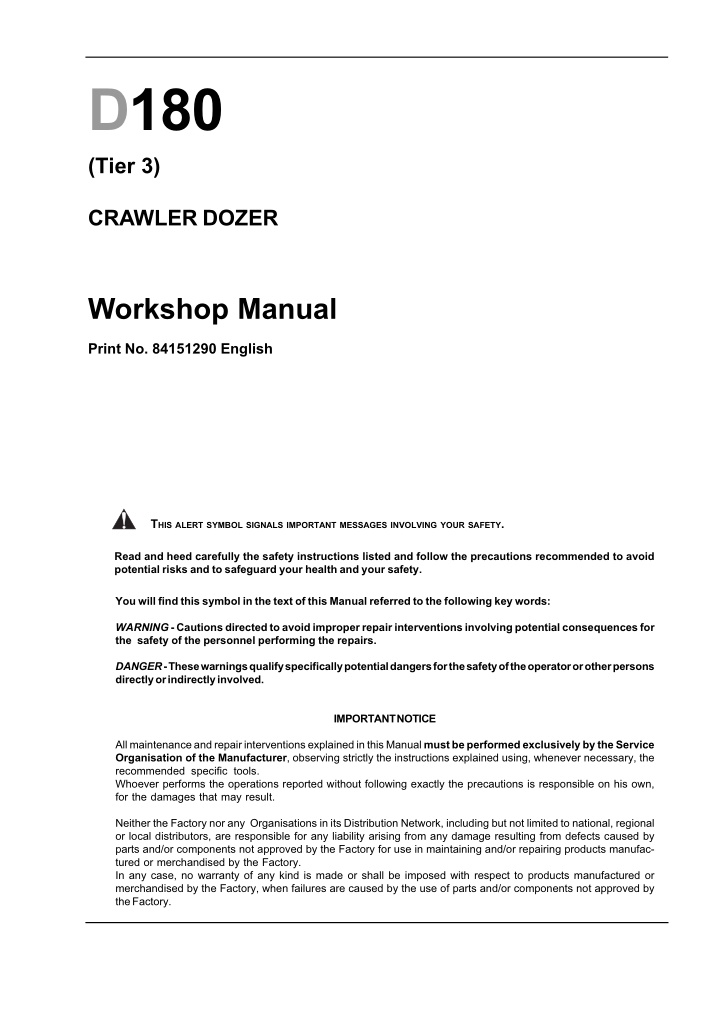
D180 (Tier 3) CRAWLER DOZER Workshop Manual Print No. 84151290 English THISALERTSYMBOLSIGNALSIMPORTANTMESSAGESINVOLVINGYOURSAFETY. Read and heed carefully the safety instructions listed and follow the precautions recommended to avoid potential risks and to safeguard your health and your safety. You will find this symbol in the text of this Manual referred to the following key words: WARNING - Cautions directed to avoid improper repair interventions involving potential consequences for the safety of the personnel performing the repairs. DANGER - These warnings qualify specifically potential dangers for the safety of the operator or other persons directly or indirectly involved. IMPORTANT NOTICE All maintenance and repair interventions explained in this Manual must be performed exclusively by the Service Organisation of the Manufacturer, observing strictly the instructions explained using, whenever necessary, the recommended specific tools. Whoever performs the operations reported without following exactly the precautions is responsible on his own, for the damages that may result. Neither the Factory nor any Organisations in its Distribution Network, including but not limited to national, regional or local distributors, are responsible for any liability arising from any damage resulting from defects caused by parts and/or components not approved by the Factory for use in maintaining and/or repairing products manufac- tured or merchandised by the Factory. In any case, no warranty of any kind is made or shall be imposed with respect to products manufactured or merchandised by the Factory, when failures are caused by the use of parts and/or components not approved by the Factory.
AVOID ACCIDENTS Most accidents, whether they occur in industry, on the farm, at home or on the road, are caused by the failure of some individuals to follow simple and fundamental safety rules and precautions. For this reason MOST ACCI- DENTS CAN BE PREVENTED by recognising the real cause and doing something aboiut it before the accident occurs. Regardless of the care used in the design and construc- tion of any type of equipment, there are many conditions that cannot be completely safeguarded against without interfering in the reasonable accessibility and efficient operation. A carefull operator is the best insurance against an accident. The complete observance of one simple rule would prevent many serious accidents. The rule is simple: never attempt to clean, lubricate or maintain a machine while it is in motion. WARNING Prior to engaging in any maintenance, adjustment or repair operation on machines having hydrauli- cally, mechanically, and/or cable controlled equip- ment (such as shovels, loaders, dozers, excavators etc.) be certain the equipment is lowered to the ground. If it is necessary to have the equipment partially or fully raised to gain access to certain items, be sure the equipment is suitably supported by means oth- er than the devices used for controlling the equip- ment.
SUMMARY GENERALITIES SECT. 0 ENGINE SECT. 1 TRANSMISSION SECT. 2 FINAL DRIVES SECT. 3 BRAKES AND STEERING DIFFERENTIAL - D180 POWER STEERING SECT. 4 BRAKES AND STEERING CLUTCHES - D180 STEERING CLUTCHES SECT. 4 BIS UNDERCARRIAGE SECT. 5 DOZING EQUIPMENT - HYDRAULIC SYSTEM D180 PS SECT. 6 DOZING EQUIPMENT - HYDRAULIC SYSTEM D180 SC SECT. 6 BIS ELECTRICAL SYSTEM SECT. 7 AIR CONDITIONING UNIT SECT. 8 D180-3R001
https://www.ebooklibonline.com Hello dear friend! Thank you very much for reading. Enter the link into your browser. The full manual is available for immediate download. https://www.ebooklibonline.com
SECTION 0 GENERALITIES TABLE OF CONTENTS SUBJECT PAGE SAFETY RULES ..........................................................................................................................................I-VIII IDENTIFICATION DATA Engine data plate........................................................................................................................................ 0-3 Vehicle Identification Plate .......................................................................................................................... 0-4 Marking and serial number.......................................................................................................................... 0-4 TABLE OF FLUID CAPACITIES..................................................................................................................... 0-5 DIMENSIONS D180 BD ................................................................................................................................ 0-6 DIMENSIONS D180 PAT ............................................................................................................................... 0-7 Technical data D180 PS - D180 SC............................................................................................................ 0-8 D180 POWER STEERING LGP .................................................................................................................. 0-24 D180 POWER STEERING LT/XLT - STEERING CLUTCHES LT/XLT ............................................................ 0-25 WEIGHT AND EQUIPMENT D180 PAT........................................................................................................ 0-26 WEIGHT MACHINE D180 PAT .................................................................................................................... 0-26 LIST OF WEIGHTS FOR MAIN SERVICE COMPONENTS ..........................................................................0-27 CENTRE OF GRAVITY TABLE.....................................................................................................................0-29 GENERAL INSTRUCTIONS..........................................................................................................................0-30 TROUBLESHOOTING ..................................................................................................................................0-35 UNITS OF MEASURE ..................................................................................................................................0-36 TABLE OF TIGHTENING TORQUES ............................................................................................................0-38
WARNING Study carefully this Manual before starting, operating, maintaining, fuelling or servicing the machine. Read and heed all safety rules before any intervention. SAFETY RULES - Do not allow unauthorised personnel to operate service or maintain this machine. Before operating a machine, always ensure that any unsafe condition has been satisfactorily remedied. - Do not wear rings, wrist watches, jewellery, loose or hanging apparels, such as ties, torn clothing, scarves, unbuttoned or unzipped jackets that can catch on mov- ing parts. Wear proper safety equipment as recom- mended for the job. Examples: hard hat, heavy gloves, ear protection, safety glasses or goggles, reflector vests, respirator. Consult your employer for specific safety equipment requirements. - Check brakes, steering and attachment controls before moving. Advise the proper maintenance authority of any malfunctioning part or system. - Be sure all protective guards or panels are in place, and all safety devices provided are in place and in good operating conditions. - Be sure exposed personnel in the area of operation are clear of the machine before moving it or its attachments. WALK COMPLETELY AROUND the machine before mounting. Sound horn. - Keep operator's compartment, stepping points, grab- rails and handles clear of foreign objects, oil, grease, mud or snow accumulation to minimise the danger of slipping or stumbling. Clean mud or grease from shoes before attempting to mount or operate the machine. - Before starting machine, check, adjust and lock the operator's seat for maximum comfort and control of the machine. - Do not jump on or off the machine. Keep two hands and one foot, or two feet and one hand in contact with step grab rails and handles at all times. - Fasten your seat belt (when provided). - Do not use controls or hoses as hand holds when climbing on or off machine. Hoses and controls are movable and do not provide a solid support. Also, controls may be inadvertently moved causing accidental machine or equipment movement. - Obey all flag signals and signs. - Due to the presence on the machine of flammable fluids, never check or fill fuel reservoirs or batteries near open flames, smoking materials or sparks. - Never attempt to operate the machine or its tools from any position other than seated in the operator's seat. - REMEMBER THAT STARTING FLUID IS FLAMMABLE. Follow strictly the recommendations printed on contain- ers and in the Operation and Maintenance Manual. - Keep head, body, limbs, hands and feet inside opera- tor's compartment at all times, to reduce exposure to hazards outside the operator's compartment. - DO NOT PUNCTURE OR BURN CONTAINERS. - Containers must be stored in fresh, well ventilated plac- es, out of reach of unauthorised persons. Follow strictly the instructions provided by the Manufacturer. - Be careful of slippery conditions on stepping points, hand rails, and on the ground. Wear safety boots or shoes that have a high slip resistant sole material. - Never use these products near open flames, smoking materials or sparks. - Do not leave the machine until it is completely stopped. - Check the seat safety belt at least twice a year. If there are signs of wear or fraying or other signs of weakness that could lead to failure, replace it. OPERATION - Do not run the engine of this machine in closed areas without proper ventilation to remove deadly exhaust gases. STARTING - NEVER START NOR OPERATE AN UNSAFE MA- CHINE. - Roll Over Protective Structures are required on loaders, dozers, graders, excavators. I
SAFETY RULES NEVER OPERATE machines without ROPS. Keep cab windows clean and repaired. - Make sure the Operator's compartment is free of foreign objects, especially if not firmly secured. Never use the machine to transport objects, unless proper securing points are provided. - When machines are operating in tandem, the pusher (rear) must be equipped with the appropriate deflectors to protect the unit in front from the air stream coming from the radiator. - When pulling or towing through a cable or chain, do not start suddenly at full throttle; take-up slack carefully. - Check monitoring instruments at start-up and frequently during operations. in case the brake pressure gauge shows a pressure lower than the minimum operating pressure, stop immediately the machine . Inspect carefully for flaws or troubles before using. - Avoid kinking chains or cables. Do not pull through a kinked chain or cable to the high stresses and possibility of failure of the kinked area. Always wear heavy gloves when handling chains or cables. - DO NOT CARRY RIDERS ON MACHINE - Study and familiarise with escape routes alternate to normal exit routes. - Be sure chains and cables are anchored and the anchor points are strong enough to handle the expected load. Keep exposed personnel clear of anchor points and cables or chains. - Seat belts are required by current regulations to be provid- ed with Roll Over Protection Structures or cabs. Keep safety belts fastened around you during operation. - For your personal protection, do not climb on or off machine while machine is in motion. - DO NOT PULL UNLESS OPERATOR's COMPARTMENT OF MACHINES INVOLVED ARE PROPERLY GUARDED AGAINST POTENTIAL CABLE OR CHAIN BACKLASH. - Make sure that exposed persons in the area of operation are clear of the machine, before starting the engine and operating the equipment. Sound horn. Obey all indications provided by flags and signals. - Be alert to soft ground conditions close to newly construct- ed walls. The fill material and weight of the machine may cause the wall collapse under the machine. - NEVER COAST the machine down grades and slopes with the transmission in neutral or neutralised. - In darkness, check area of operation carefully before moving in with machine. Use all lights provided. Do not move into area of restricted visibility. Choose and shift into the most appropriate gear to keep the speed required, thus preventing any loss of control. - If engine has a tendency to stall for any reason under load or idle, report this for adjustment to proper maintenance authority immediately. Do not continue to operate ma- chine, until condition has been corrected. - Do not operate machinery in a condition of extreme fatigue or illness. Be especially careful towards the end of working shift. - Do not operate machine with brakes out of adjustment. - On machines supplied with suction radiator fans, be sure to periodically check engine exhaust parts for leaks, as exhaust fumes are dangerous to the operator. - Operate the machine at speeds slow enough to ensure complete control at all times. - In case of closed type cabs, always keep an opening with the outside, to ensure a constant air circulation. - Travel slowly over rough terrain, on slopes or near drop- offs, in congested areas or on ice or slippery surfaces. - Operators must know thoroughly the performances of the machine they are operating. When working on slopes or near sudden level drops of the terrain, avoid areas where ground is loose or soft since rolling-over or loss of control of machine could result. - When backing, always look to where the machine is to be moved. Be alert to the position of exposed personnel. DO NOT OPERATE if exposed personnel enter the immediate work area. STOP THE MACHINE. - Maintain a safe distance from other machines. Provide sufficient clearance for ground and visibility conditions. Yield right-of-way to loaded machines. - Where noise exposure exceeds 90 dBA for 8 hours, wear approved ear protection. - When counterweights are provided, do not work machine if they have been removed. - Maintain clear vision of areas of travel or work. II
SECTION 1 ENGINE TABLE OF CONTENTS SUBJECT PAGE CHAPTER GENERAL SPECIFICATIONS .................................................................................................. 1-3 Identification of the engine ..................................................................................................... 1-4 1.1 SERIES "C" ENGINE DATA ..................................................................................................... 1-5 1.2 DIAGRAMS OF SERIES "C" ENGINE ..................................................................................... 1-7 1.3 MOUNTING OF ENGINE ON FRAME .....................................................................................1-11 Engine/converter removal and installation ............................................................................1-12 Removal of the radiator group ..............................................................................................1-24 Removal of silencer group ...................................................................................................1-26 Removal of converter group..................................................................................................1-27 Reinstalling the converter group...........................................................................................1-28 Reinstalling the silencer group ............................................................................................1-30 Reinstalling the radiator group .............................................................................................1-31 Reinstalling the engine group assembly ..............................................................................1-33 1.4 DIAGNOSTICS WITH BLINK CODE ....................................................................................... 1-45 1.5
1 - 3 ENGINE D180 1.1 GENERAL SPECIFICATIONS 1. The engine is a diesel for heavy duty applications characterised by several design concepts tend- ing towards simplicity and a high compactness. 1850-3R002 Series C Length Width Height Weight mm 1050 41.3 in mm 685 in mm 945 in kg 550 1212.5 lb 26.9 37.2 2. The engine incorporates, in a single solution, all the most important characteristics and advantag- es of modern diesel technology. Technology In-line cylinders Water cooled 4 stroke Turbocharged Afterc-ooled Direct injection Metric dimensions Air flow cooling 3. The engine has been entirely designed with met- ric dimensions. the only discrepancy with these specifications involves the use of connections for pipes and plugs with SAE standards. The speci- fications of accessories change depending upon the Supplier. Technical publications list metric values with the equivalent SAE values. Engine components Metric specifications Pipes connections and plugs SAE standards Carefully read personal and machine SAFETY PRECAUTIONS at the beginning of this Manual
1 - 4 D180 ENGINE IDENTIFICATION OF THE ENGINE 1850-M0044 Engine data plate The engine data plate provides the identification data and other important information about the engine. Have the engine data here below available when con- tacting a Iveco Authorised Repair Centre. The infor- mation data on the plate are compulsory when pro- curing Spare Parts. Note Do not change the engine data plate unless authorised by IVECO. Specifications of engine series The total displacement of the engine is 6.7 litres (1.7 gal), the bore is 104 mm (4 in) and the stroke 132 mm (5.1 in). The firing order is the same as for the other in-line, 6 cylinder Iveco engines, 1-5-3-6-2-4. Total displacement Bore Stroke Firing order 6,7 litri 104 mm 132 mm 1-5-3-6-2-4 Carefully read personal and machine SAFETY PRECAUTIONS at the beginning of this Manual
1 - 5 ENGINE D180 1.2 ENGINE DATA Generalities D180 LT/XLT D180 LGP Bore:............................................................................... 104 mm [4.0 in]......................... 104 mm [4.49 in] Stroke: ............................................................................ 132 mm [5.1 in]......................... 132 mm [5.32 in] Total displacement: ......................................................... 6.7 L [408.8 in3]...........................6.7 L [408.8 in3] Net flywheel power (ISO 9249) .................................... 196 HP / 146 kW........................ 210 HP / 157 kW Low idle ......................................................................... 780 920 rpm............................... 780 920 rpm High idle..................................................................... 2030 2170 rpm........................... 2030 2170 rpm Implem. stall ...............................................................2020 2160 rpm........................... 2020 2160 rpm Torque converter / transmission stall ...........................1710 1850 rpm........................... 1785 1925 rpm Total stall ....................................................................1640 1840 rpm........................... 1725 1925 rpm Maximum torque ..................................................................... 860Nm....................952Nm A 1400 min-1 Compression ratio ........................................................................16.5 : 1....................................... 16.5 : 1 Firing order: ...........................................................................1-5-3-6-2-4................................. 1-5-3-6-2-4 Valve clearance Intake: .................................................................. 0.30 mm [0.012 in]......................0.30 mm [0.012 in] Exhaust: ............................................................... 0.61 mm [0.024 in]......................0.61 mm [0.024 in] Engine rotation (seen from front side of engine): .................... Clockwise................................... Clockwise Intake .....................................................Turbocharged with after-cooled.. Turbocharged with after-cooled Carefully read personal and machine SAFETY PRECAUTIONS at the beginning of this Manual
1 - 7 ENGINE D180 1.3 DIAGRAMS OF ENGINE The illustrations here below provide information on the engine components, the location of filters, the drain- ing points and the access locations for engine instru- mentation and controls. The illustrations and the configuration of the compo- nents shown in these diagrams are of a general na- ture. The locations of some components change de- pending upon the application and the installation. For the removal, testing, overhaul and installation of the engine, please refer to the Workshop Manual IVECO. Engine oil dipstick High pressure fuel pipes Cold start device Fan pulley Air inlet manifold Rear lifting bracket Electronic controller Dumper Crankshaft pulley High pressure fuel pump Fuel filter Pressure sensor engine oil Engine flywheel cover Oil draining plug 1850-3R004 View from left side Carefully read personal and machine SAFETY PRECAUTIONS at the beginning of this Manual
1 - 8 D180 ENGINE Water temperature Turbocharger lube pipe Tappet cover Turbocharger Coolant outlet Exhaust manifold RPM sensor engine Lube oil filter Coolant inlet Turbocharger oil draining Starter motor 1850-3R005 View from left right Carefully read personal and machine SAFETY PRECAUTIONS at the beginning of this Manual
1 - 9 ENGINE D180 Centring bearing Flyweel Flex disc mountng holes Flyweel housing 1850-3R078 Rear view Fan pulley Turbocharger air intake Belt tensioner Water pump Oil sump 1850-3R079 Front view Carefully read personal and machine SAFETY PRECAUTIONS at the beginning of this Manual
1 - 10 D180 ENGINE Turbocharger air outlet Turbocharger air inlet Turbocharger exhaust outlet Engine oil filter neck Common rail 1850-3R080 View from above Carefully read personal and machine SAFETY PRECAUTIONS at the beginning of this Manual
1 - 11 ENGINE D180 1.4 MOUNTING OF ENGINE ON FRAME C2 C1 C2 C3 D180-3R003 Tightening torques C1. Self-locking nut M24 x 2 .............. 108 daNm (796.3 lbf.ft) C2. Screw TE M12 x 1.75 ...................... 11 daNm (81.1 lbf.ft) C3. Self-locking nut M16 x 1.5 ............... 30 daNm (22.1 lbf.ft) Carefully read personal and machine SAFETY PRECAUTIONS at the beginning of this Manual
1 - 12 D180 ENGINE ENGINE/CONVERTER REMOVAL AND INSTALLATION REMOVAL OF ENGINE GROUP ASSEMBLY Turn the STARTER SWITCH into OFF and place the "DO NOT START" notice as indicated in the figure. WARNING Do not allow unauthorized persons to repair or maintain this machine. Read carefully the Operation and Maintenance Manual prior to starting, operating, maintaining or refueling and repairing the machine. DO NOT OPERATE D180-3R009 Oil draining Remove plug (1) from the bottom of the machine, with the transmission oil warm, and let it drain into a container with a 40 liter (10 USG) capacity, at least. DANGER 1 Pressurized fluid: before removing the plug or the cover turn it slowly to release the pressure. See the Instruction Manual. D180-2M195 To facilitate the draining, open the right panel under the cab and loosen plug (2) from the transmission oil filler neck. 2 1850-3R922 Carefully read personal and machine SAFETY PRECAUTIONS at the beginning of this Manual
Suggest: If the above button click is invalid. Please download this document first, and then click the above link to download the complete manual. Thank you so much for reading
1 - 13 ENGINE D180 With engine cold, drain the coolant from the radiator by opening the valve indicated in the figure, located at the bottom of the radiator itself. To facilitate the draining, remove the coolant filler cap on the radiator. 1850-2R435 Remove the windshield washer liquid pipes (1) from the engine hood upper panels. WARNING 1 Handle all components with great care. Never place hands or fingers between parts. Wear approved protective clothing such as glasses, gloves and safety shoes. 1850-2R431 Remove the plastic protection caps (2) (q.ty 4) of the screws securing the engine hood. 2 1850-2R432 Remove the engine hood securing screws (3) (q.ty 4) complete with washers and vibration damper rubber rings. 3 1850-2R433 Carefully read personal and machine SAFETY PRECAUTIONS at the beginning of this Manual
https://www.ebooklibonline.com Hello dear friend! Thank you very much for reading. Enter the link into your browser. The full manual is available for immediate download. https://www.ebooklibonline.com

