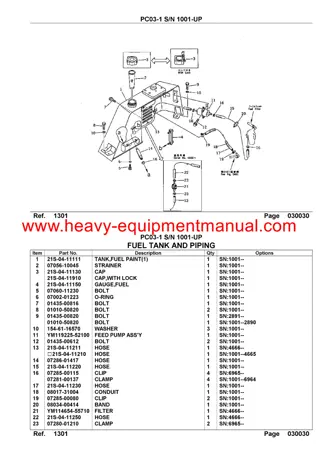
New Holland D180C BD Crawler Dozer Service Repair Manual Instant Download
New Holland D180C BD Crawler Dozer Service Repair Manual Instant Download
Download Presentation

Please find below an Image/Link to download the presentation.
The content on the website is provided AS IS for your information and personal use only. It may not be sold, licensed, or shared on other websites without obtaining consent from the author. If you encounter any issues during the download, it is possible that the publisher has removed the file from their server.
You are allowed to download the files provided on this website for personal or commercial use, subject to the condition that they are used lawfully. All files are the property of their respective owners.
The content on the website is provided AS IS for your information and personal use only. It may not be sold, licensed, or shared on other websites without obtaining consent from the author.
E N D
Presentation Transcript
SERVICE MANUAL SERVICE MANUAL D180C Crawler Dozers D180C Crawler Dozers 1/1 Part Number 71114549 1st Edition English 03/2015 Part Number 71114549 1st Edition English 03/2015 Printed in Brazil Copyright 2015 CNH Industrial Latin America LTDA. All Rights Reserved.
SERVICE MANUAL D180C BD D180C PAT 71114549 16/03/2015 EN
Contents INTRODUCTION Engine....................................................................................... 10 [10.001] Engine and crankcase ............................................................. 10.1 [10.216] Fuel tanks .......................................................................... 10.2 [10.202] Air cleaners and lines .............................................................. 10.3 [10.250] Turbocharger and lines............................................................. 10.4 [10.254] Intake and exhaust manifolds and muffler ......................................... 10.5 [10.400] Engine cooling system ............................................................. 10.6 [10.414] Fan and drive ...................................................................... 10.7 [10.310] Aftercooler.......................................................................... 10.8 [10.304] Engine lubrication system.......................................................... 10.9 Hydrostatic drive......................................................................... 29 [29.218] Pump and motor components...................................................... 29.1 Brakes and controls .................................................................... 33 [33.110] Parking brake or parking lock ...................................................... 33.1 [33.202] Hydraulic service brakes ........................................................... 33.2 Hydraulic systems....................................................................... 35 [35.300] Reservoir, cooler, and filters........................................................ 35.1 [35.104] Fixed displacement pump.......................................................... 35.2 [35.106] Variable displacement pump ....................................................... 35.3 [35.105] Charge pump....................................................................... 35.4 [35.359] Main control valve.................................................................. 35.5 [35.741] Dozer blade cylinders .............................................................. 35.6 [35.752] Hydraulic fan drive cooling system................................................. 35.7 [35.000] Hydraulic systems.................................................................. 35.8 Frames and ballasting................................................................. 39 71114549 16/03/2015
https://www.ebooklibonline.com Hello dear friend! Thank you very much for reading. Enter the link into your browser. The full manual is available for immediate download. https://www.ebooklibonline.com
[39.100] Frame .............................................................................. 39.1 Tracks and track suspension........................................................ 48 [48.134] Track tension units ................................................................. 48.1 [48.140] Dropbox and final drive ............................................................ 48.2 Cab climate control..................................................................... 50 [50.100] Heating............................................................................. 50.1 [50.104] Ventilation .......................................................................... 50.2 Electrical systems....................................................................... 55 [55.000] Electrical system ................................................................... 55.1 [55.011] Fuel tank system ................................................................... 55.2 [55.014] Engine intake and exhaust system................................................. 55.3 [55.015] Engine control system.............................................................. 55.4 [55.030] Service brake electrical system .................................................... 55.5 [55.050] Heating, Ventilation, and Air-Conditioning (HVAC) control system................. 55.6 [55.100] Harnesses and connectors......................................................... 55.7 [55.201] Engine starting system............................................................. 55.8 [55.202] Cold start aid ....................................................................... 55.9 [55.301] Alternator......................................................................... 55.10 [55.302] Battery............................................................................ 55.11 [55.512] Cab controls...................................................................... 55.12 [55.518] Wiper and washer system........................................................ 55.13 [55.DTC] FAULT CODES.................................................................. 55.14 Dozer blade and arm................................................................... 86 [86.110] Dozer blade ........................................................................ 86.1 Tools......................................................................................... 89 [89.128] Ripper assembly ................................................................... 89.1 Platform, cab, bodywork, and decals............................................. 90 [90.150] Cab................................................................................. 90.1 71114549 16/03/2015
[90.114] Operator protections ............................................................... 90.2 [90.100] Engine hood and panels ........................................................... 90.3 71114549 16/03/2015
INTRODUCTION 71114549 16/03/2015 1
INTRODUCTION Safety rules LA D180C Personal safety This is the safety alert symbol. It is used to alert you to potential personal injury hazards. Obey all safety messages that follow this symbol to avoid possible death or injury. Throughout this manual you will find the signal words DANGER, WARNING, and CAUTION followed by special in- structions. These precautions are intended for the personal safety of you and those working with you. Read and understand all the safety messages in this manual before you operate or service the machine. DANGER indicates a hazardous situation that, if not avoided, will result in death or serious injury. WARNING indicates a hazardous situation that, if not avoided, could result in death or serious injury. CAUTION indicates a hazardous situation that, if not avoided, could result in minor or moderate injury. FAILURE TO FOLLOW DANGER, WARNING, AND CAUTION MESSAGES COULD RESULT IN DEATH OR SERIOUS INJURY. Machine safety NOTICE: Notice indicates a situation that, if not avoided, could result in machine or property damage. Throughout this manual you will find the signal word Notice followed by special instructions to prevent machine or property damage. The word Notice is used to address practices not related to personal safety. Information NOTE: Note indicates additional information that clarifies steps, procedures, or other information in this manual. Throughout this manual you will find the word Note followed by additional information about a step, procedure, or other information in the manual. The word Note is not intended to address personal safety or property damage. 71114549 16/03/2015 3
INTRODUCTION Safety rules - Ecology and the environment LA D180C Soil, air, and water quality is important for all industries and life in general. When legislation does not yet rule the treatment of some of the substances that advanced technology requires, sound judgment should govern the use and disposal of products of a chemical and petrochemical nature. Familiarize yourself with the relative legislation applicable to your country, and make sure that you understand this legislation. Where no legislation exists, obtain information from suppliers of oils, filters, batteries, fuels, anti-freeze, cleaning agents, etc., with regard to the effect of these substances on man and nature and how to safely store, use, and dispose of these substances. Helpful hints Avoid the use of cans or other inappropriate pressurized fuel delivery systems to fill tanks. Such delivery systems may cause considerable spillage. In general, avoid skin contact with all fuels, oils, acids, solvents, etc. Most of these products contain substances that may be harmful to your health. Modern oils contain additives. Do not burn contaminated fuels and or waste oils in ordinary heating systems. Avoid spillage when you drain fluids such as used engine coolant mixtures, engine oil, hydraulic fluid, brake fluid, etc. Do not mix drained brake fluids or fuels with lubricants. Store all drained fluids safely until you can dispose of the fluids in a proper way that complies with all local legislation and available resources. Do not allow coolant mixtures to get into the soil. Collect and dispose of coolant mixtures properly. The air-conditioning system contains gases that should not be released into the atmosphere. Consult an air-condi- tioning specialist or use a special extractor to recharge the system properly. Repair any leaks or defects in the engine cooling system or hydraulic system immediately. Do not increase the pressure in a pressurized circuit as this may lead to a component failure. Protect hoses during welding. Penetrating weld splatter may burn a hole or weaken hoses, allowing the loss of oils, coolant, etc. Battery recycling Batteries and electric accumulators contain several substances that can have a harmful effect on the environment if the batteries are not properly recycled after use. Improper disposal of batteries can contaminate the soil, groundwater, and waterways. NEW HOLLAND CONSTRUCTION strongly recommends that you return all used batteries to a NEW HOLLAND CONSTRUCTION dealer, who will dispose of the used batteries or recycle the used batteries properly. In some countries, this is a legal requirement. Mandatory battery recycling NOTE: The following requirements are mandatory in Brazil. Batteries are made of lead plates and a sulfuric acid solution. Because batteries contain heavy metals such as lead, CONAMA Resolution 401/2008 requires you to return all used batteries to the battery dealer when you replace any batteries. Do not dispose of batteries in your household garbage. Points of sale are obliged to: Accept the return of your used batteries Store the returned batteries in a suitable location Send the returned batteries to the battery manufacturer for recycling 71114549 16/03/2015 4
INTRODUCTION Safety rules LA D180C General safety rules Use caution when operating the machine on slopes. Raised equipment, full tanks and other loads will change the center of gravity of the machine. The machine can tip or roll over when near ditches and embankments or uneven surfaces. Never permit anyone other than the operator to ride on the machine. Never operate the machine under the influence of alcohol, drugs, or while otherwise impaired. When digging or using ground engaging attachments be aware of buried cables. Contact local utilities to determine the locations of services. Pay attention to overhead power lines and hanging obstacles. High voltage lines may require significant clearance for safety. Hydraulic oil or diesel fuel leaking under pressure can penetrate the skin, causing serious injury or infection. DO NOT use your hand to check for leaks. Use a piece of cardboard or paper. Stop engine, remove key and relieve the pressure before connecting or disconnecting fluid lines. Make sure all components are in good condition and tighten all connections before starting the engine or pressur- izing the system. If hydraulic fluid or diesel fuel penetrates the skin, seek medical attention immediately. Continuous long term contact with hydraulic fluid may cause skin cancer. Avoid long term contact and wash the skin promptly with soap and water. Keep clear of moving parts. Loose clothing, jewelry, watches, long hair, and other loose or hanging items can become entangled in moving parts. Wear protective equipment when appropriate. DO NOT attempt to remove material from any part of the machine while it is being operated or components are in motion. Make sure all guards and shields are in good condition and properly installed before operating the machine. Never operate the machine with shields removed. Always close access doors or panels before operating the machine. Dirty or slippery steps, ladders, walkways, and platforms can cause falls. Make sure these surfaces remain clean and clear of debris. A person or pet within the operating area of a machine can be struck or crushed by the machine or its equipment. DO NOT allow anyone to enter the work area. Raised equipment and/or loads can fall unexpectedly and crush persons underneath. Never allow anyone to enter the area underneath raised equipment during operation. Never operate engine in enclosed spaces as harmful exhaust gases may build up. Before starting the machine, be sure that all controls are in neutral or park lock position. Start the engine only from the operator s seat. If the safety start switch is bypassed, the engine can start with the transmission in gear. Do not connect or short across terminals on the starter solenoid. Attach jumper cables as described in the manual. Starting in gear may cause death or serious injury. Always keep windows, mirrors, all lighting, and Slow Moving Vehicle (SMV) emblem clean to provide the best possible visibility while operating the machine. Operate controls only when seated in the operator s seat, except for those controls expressly intended for use from other locations. 71114549 16/03/2015 6
INTRODUCTION Before leaving the machine: 1. Park machine on a firm level surface. 2. Put all controls in neutral or park lock position. 3. Engage park brake. Use wheel chocks if required. 4. Lower all hydraulic equipment Implements, header, etc. 5. Turn off engine and remove key. When, due to exceptional circumstances, you would decide to keep the engine running after leaving the operator s station, then the following precautions must be followed: 1. Bring the engine to low idle speed. 2. Disengage all drive systems. WARNING Some components may continue to run down after disengaging drive systems. Make sure all drive systems are fully disengaged. Failure to comply could result in death or serious injury. 3. W0113A Shift the transmission into neutral. 4. Apply the parking brake. General maintenance safety Keep area used for servicing the machine clean and dry. Clean up spilled fluids. Service machine on a firm level surface. Install guards and shields after servicing the machine. Close all access doors and install all panels after servicing the machine. Do not attempt to clean, lubricate, clear obstructions or make adjustments to the machine while it is in motion or while the engine is running. Always make sure working area is clear of tools, parts, other persons and pets before you start operating the machine. Unsupported hydraulic cylinders can lose pressure and drop the equipment causing a crushing hazard. Do not leave equipment in a raised position while parked or during service, unless securely supported. Jack or lift the machine only at jack or lift points indicated in this manual. Incorrect towing procedures can cause accidents. When towing a disabled machine follow the procedure in this man- ual. Use only rigid tow bars. Stop the engine, remove key and relieve pressure before disconnecting or connecting fluid lines. Stop the engine and remove key before disconnecting or connecting electrical connections. Scalding can result from incorrect removal of coolant caps. Cooling system operates under pressure. Hot coolant can spray out if a cap is removed while the system is hot. Allow system to cool before removing cap. When removing a cap turn it slowly to allow pressure to escape before completely removing the cap. Replace damaged or worn tubes, hoses, electrical wiring, etc. Engine, transmission, exhaust components, and hydraulic lines may become hot during operation. Take care when servicing such components. Allow surfaces to cool before handling or disconnecting hot components. Wear protective equipment when appropriate. When welding, follow the instructions in the manual. Always disconnect the battery before welding on the machine. Always wash your hands after handling battery components. 71114549 16/03/2015 7
SERVICE MANUAL Engine D180C BD D180C PAT 71114549 16/03/2015 10
Engine - Engine and crankcase Engine - Remove LA D180C Prior operation: Frame - Remove (39.100) NOTICE: The engine weighs approximately 631 kg (1391 lb). Use appropriate lifting equipment to prevent personal injury or property damage. NOTICE: The engine must be balanced as shown, or personal injury or property damage will occur. 1. Attach an appropriate lifting device to the engine lift points. 2. Support the front of the hydraulic pump stack with an appropriate lifting device or stand. 3. Remove the bolts and washers (1) from the right front engine-to-frame cradle mount and the left front engine- to-frame cradle mount. 1 RAIL14DOZ0447AA 4. Remove the mounting bolts and washers (1) from the left side engine-to-frame cradle mounting bracket (2). Remove the mounting bracket. 2 RAIL14DOZ0209AA 5. Remove the mounting bolts and washers (1) from the right side engine-to-frame cradle mounting bracket (2). Remove the bracket. 3 RAIL14DOZ0202AA 71114549 16/03/2015 10.1 [10.001] / 3
Engine - Engine and crankcase 6. Remove the mounting bolts and washers (1) from the engine-to-pump stack adapter plate (2). 7. Slowly move the engine forward to separate it from the hydrostatic drive pump stack, and remove the engine from the frame cradle. 4 RAIL14DOZ0203AA 8. Remove the tandem pump flexible coupling assembly from the flywheel. Next operation: Engine - Install (10.001) 71114549 16/03/2015 10.1 [10.001] / 4
Engine - Engine and crankcase Engine - Install LA D180C Prior operation: Engine - Remove (10.001) 1. Attach the tandem pump flexible coupling assembly to the flywheel. Torque the bolts to 41 - 50 N m (30 - 37 lb ft) 2. Slowly lower the engine into the frame cradle and con- nect the engine to the hydrostatic drive pump stack. 3. Install the mounting bolts and washers (1) into the en- gine-to-pump stack adapter plate (2). Torque the bolts to 46 - 62 N m (34 - 46 lb ft). 1 RAIL14DOZ0203AA 4. Use a level and verify that the engine mounting frame cradle is sitting on a level surface. NOTE: Before applying the torque to the mid engine-to-frame cradle mount bracket bolts and the front engine-to- mount frame cradle bolts to their final specification, make sure that the frame cradle is level. 5. Install the right side engine-to-frame cradle mounting bracket. Apply LOCTITE 242 to the engine-to-frame cradle mounting bracket bolts. Torque the three bolts (1) 91 - 123 N m (67 - 91 lb ft) to the adapter plate, and the three bolts (2) 225 - 305 N m (166 - 225 lb ft) to the right side engine-to-frame cradle mounting bracket (3). 2 RAIL14DOZ0202AA 71114549 16/03/2015 10.1 [10.001] / 5
Engine - Engine and crankcase 6. Install the left side engine-to-frame cradle mounting bracket. Apply LOCTITE 242 to the engine-to-frame cradle mounting bracket bolts. Torque the three bolts (1) 91 - 123 N m (67 - 91 lb ft) to the adapter plate, and the three bolts (2) 225 - 305 N m (166 - 225 lb ft) to the left side engine-to-frame cradle mounting bracket (3). 3 RAIL14DOZ0209AA 7. Install the bolts and washers (1) into the right front en- gine-to-frame cradle mount and the left front engine-to- frame cradle mount. Torque the bolts to 107 - 123 N m (79 - 91 lb ft). 4 RAIL14DOZ0447AA 8. Remove the support from the hydraulic pump stack. Remove the lifting device from the engine. Next operation: Frame - Install (39.100) 71114549 16/03/2015 10.1 [10.001] / 6
Engine - Fuel tanks Fuel tank - Remove LA D180C 1. Removethecabfromthemachine. SeeCab-Remove (90.150). 2. Removefourboltsandwashers(1)andremovethefuel / Diesel Exhaust Fluid (DEF) drain hose access panel (2) from the left side of the machine. 1 RAIL14DOZ0141AA 3. Remove the fuel tank drain hose cap (1) from the fuel tank drain hose (2). 2 RAIL14DOZ0142AA 4. Open the fuel tank drain valve and drain the fuel into a suitable container for storage. Close the drain valve when complete. 3 RAIL14DOZ0144AA 71114549 16/03/2015 10.2 [10.216] / 3
Suggest: If the above button click is invalid. Please download this document first, and then click the above link to download the complete manual. Thank you so much for reading
Engine - Fuel tanks 5. Loosen the drain hose clamp (1) and remove the drain hose (2) from the drain valve (3). 4 RAIL14DOZ0144AA 6. Install the fuel tank drain hose cap (1) to the fuel tank drain hose (2). 5 RAIL14DOZ0142AA 7. Tag and disconnect the fuel supply (1) and the fuel re- turn (2) lines from the top of the fuel tank. Close all openings to prevent fuel loss or contamination. 6 RAIL14DOZ0143AA 8. Removethefuelsupply(1)andthefuelreturn(2)hoses from the four retaining clips (3) at the top rear of the fuel tank. 7 RAIL14DOZ0145AA 71114549 16/03/2015 10.2 [10.216] / 4
https://www.ebooklibonline.com Hello dear friend! Thank you very much for reading. Enter the link into your browser. The full manual is available for immediate download. https://www.ebooklibonline.com

