New Holland FR650 Tier 4B (final) Forage Harvester Service Repair Manual Instant Download
New Holland FR650 Tier 4B (final) Forage Harvester Service Repair Manual Instant Download
Download Presentation

Please find below an Image/Link to download the presentation.
The content on the website is provided AS IS for your information and personal use only. It may not be sold, licensed, or shared on other websites without obtaining consent from the author. If you encounter any issues during the download, it is possible that the publisher has removed the file from their server.
You are allowed to download the files provided on this website for personal or commercial use, subject to the condition that they are used lawfully. All files are the property of their respective owners.
The content on the website is provided AS IS for your information and personal use only. It may not be sold, licensed, or shared on other websites without obtaining consent from the author.
E N D
Presentation Transcript
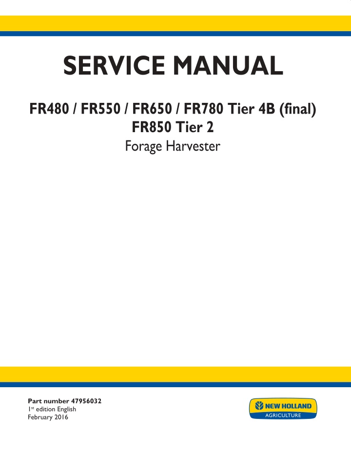
SERVICE MANUAL FR480 / FR550 / FR650 / FR780 Tier 4B (final) FR850 Tier 2 Forage Harvester Part number 47956032 1st edition English February 2016 Printed in U.S.A. 2016 CNH Industrial Belgium N.V. All Rights Reserved. New Holland is a trademark registered in the United States and many other countries, owned by or licensed to CNH Industrial N.V., its subsidiaries or affiliates.
SERVICE MANUAL FR480 Forage Cruiser Cursor 13, TIER 4B FR550 Forage Cruiser Cursor 13, TIER 4B FR650 Forage Cruiser Cursor 16, TIER 4B FR780 Forage Cruiser Cursor 16, TIER 4B FR850 Forage Cruiser Vector, TIER2 47956032 16/02/2016 EN
Link Product / Engine Product Market Product North America Engine FR480 Forage Cruiser Cursor 13, TIER 4B FR550 Forage Cruiser Cursor 13, TIER 4B FR650 Forage Cruiser Cursor 16, TIER 4B FR780 Forage Cruiser Cursor 16, TIER 4B FR850 Forage Cruiser Vector, TIER2 F3HFE613H*B007 North America F3H FE613F*B007 North America F3JFE613A*B005 North America F3JFE613B*B006 North America FVAE2884X*B200 47956032 16/02/2016
https://www.ebooklibonline.com Hello dear friend! Thank you very much for reading. Enter the link into your browser. The full manual is available for immediate download. https://www.ebooklibonline.com
Contents INTRODUCTION Engine....................................................................................... 10 [10.001] Engine and crankcase ............................................................. 10.1 [10.218] Fuel injection system............................................................... 10.2 [10.400] Engine cooling system ............................................................. 10.3 [10.414] Fan and drive ...................................................................... 10.4 [10.418] Rotary screen ...................................................................... 10.5 Main gearbox and drive............................................................... 14 [14.100] Main gearbox and drive ............................................................ 14.1 Transmission.............................................................................. 21 [21.114] Mechanical transmission ........................................................... 21.1 [21.120] Gearbox............................................................................ 21.2 [21.130] Mechanical transmission external controls......................................... 21.3 [21.100] Mechanical transmission lubrication system ....................................... 21.4 [21.145] Gearbox internal components...................................................... 21.5 [21.182] Differential.......................................................................... 21.6 Four-Wheel Drive (4WD) system .................................................. 23 [23.101] Mechanical control ................................................................. 23.1 [23.304] Four-Wheel Drive (4WD) gearbox ................................................. 23.2 Front axle system ....................................................................... 25 [25.100] Powered front axle ................................................................. 25.1 [25.102] Front bevel gear set and differential ............................................... 25.2 [25.310] Final drives......................................................................... 25.3 Rear axle system........................................................................ 27 [27.450] Rear-powered steerable axle ...................................................... 27.1 [27.550] Non-powered rear axle............................................................. 27.2 47956032 16/02/2016
Hydrostatic drive......................................................................... 29 [29.100] Transmission and steering hydrostatic control..................................... 29.1 [29.218] Pump and motor components...................................................... 29.2 [29.202] Hydrostatic transmission ........................................................... 29.3 Brakes and controls .................................................................... 33 [33.202] Hydraulic service brakes ........................................................... 33.1 [33.110] Parking brake or parking lock ...................................................... 33.2 Hydraulic systems....................................................................... 35 [35.000] Hydraulic systems.................................................................. 35.1 [35.102] Pump control valves................................................................ 35.2 [35.106] Variable displacement pump ....................................................... 35.3 [35.204] Remote control valves ............................................................. 35.4 [35.300] Reservoir, cooler, and filters........................................................ 35.5 [35.359] Main control valve.................................................................. 35.6 [35.350] Safety and main relief valves ...................................................... 35.7 [35.600] High flow hydraulics................................................................ 35.8 [35.410] Header or attachment height system .............................................. 35.9 [35.602] Header or attachment leveling system........................................... 35.10 [35.514] Upper feed roll gearbox system.................................................. 35.11 [35.516] Cutterhead drive system ......................................................... 35.12 [35.530] Spout rotation circuit ............................................................. 35.13 [35.532] Spout raising system............................................................. 35.14 [35.534] Spout deflector system........................................................... 35.15 Steering..................................................................................... 41 [41.101] Steering control .................................................................... 41.1 [41.200] Hydraulic control components...................................................... 41.2 [41.206] Pump............................................................................... 41.3 [41.216] Cylinders ........................................................................... 41.4 47956032 16/02/2016
[41.432] Autoguidance steering ............................................................. 41.5 Wheels...................................................................................... 44 [44.511] Front wheels........................................................................ 44.1 [44.520] Rear wheels........................................................................ 44.2 Cab climate control..................................................................... 50 [50.100] Heating............................................................................. 50.1 [50.200] Air conditioning..................................................................... 50.2 Electrical systems....................................................................... 55 [55.000] Electrical system ................................................................... 55.1 [55.100] Harnesses and connectors......................................................... 55.2 [55.015] Engine control system.............................................................. 55.3 [55.010] Fuel injection system............................................................... 55.4 [55.014] Engine intake and exhaust system................................................. 55.5 [55.012] Engine cooling system ............................................................. 55.6 [55.013] Engine oil system .................................................................. 55.7 [55.301] Alternator........................................................................... 55.8 [55.512] Cab controls........................................................................ 55.9 [55.640] Electronic modules............................................................... 55.10 [55.610] Ground speed control ............................................................ 55.11 [55.019] Hydrostatic drive control system ................................................. 55.12 [55.051] Cab Heating, Ventilation, and Air-Conditioning (HVAC) controls................. 55.13 [55.050] Heating, Ventilation, and Air-Conditioning (HVAC) control system............... 55.14 [55.421] Feeding control system .......................................................... 55.15 [55.820] Chopping and cutting control systems ........................................... 55.16 [55.830] Rotary screen drive and cleaning ................................................ 55.17 [55.680] Autopilot/Autoguidance .......................................................... 55.18 [55.450] Ejecting control system .......................................................... 55.19 [55.408] Warning indicators, alarms, and instruments .................................... 55.20 47956032 16/02/2016
[55.DTC] FAULT CODES.................................................................. 55.21 Attachments/Headers.................................................................. 58 [58.900] Belt feeding ........................................................................ 58.1 Product feeding.......................................................................... 60 [60.103] Lower feed rolls .................................................................... 60.1 [60.107] Upper feed rolls .................................................................... 60.2 [60.155] Metal detector...................................................................... 60.3 Chopping................................................................................... 64 [64.100] Cutterhead ......................................................................... 64.1 [64.106] Drum ............................................................................... 64.2 [64.130] Drum gearbox...................................................................... 64.3 [64.140] Sharpening system................................................................. 64.4 [64.150] Shearbar ........................................................................... 64.5 [64.160] Crop processor..................................................................... 64.6 [64.170] Transition channel/concave and lever ............................................. 64.7 Ejection..................................................................................... 70 [70.120] Blower.............................................................................. 70.1 [70.140] Spout............................................................................... 70.2 Platform, cab, bodywork, and decals............................................. 90 [90.105] Machine shields and guards ....................................................... 90.1 [90.150] Cab................................................................................. 90.2 [90.151] Cab interior......................................................................... 90.3 47956032 16/02/2016
INTRODUCTION 47956032 16/02/2016 1
INTRODUCTION Safety rules NA NA NA NA NA FR480 Forage Cruiser FR550 Forage Cruiser FR650 Forage Cruiser FR780 Forage Cruiser FR850 Forage Cruiser Personal safety This is the safety alert symbol. It is used to alert you to potential personal injury hazards. Obey all safety messages that follow this symbol to avoid possible death or injury. Throughout this manual you will find the signal words DANGER, WARNING, and CAUTION followed by special in- structions. These precautions are intended for the personal safety of you and those working with you. Read and understand all the safety messages in this manual before you operate or service the machine. DANGER indicates a hazardous situation that, if not avoided, will result in death or serious injury. WARNING indicates a hazardous situation that, if not avoided, could result in death or serious injury. CAUTION indicates a hazardous situation that, if not avoided, could result in minor or moderate injury. FAILURE TO FOLLOW DANGER, WARNING, AND CAUTION MESSAGES COULD RESULT IN DEATH OR SERIOUS INJURY. Machine safety NOTICE: Notice indicates a situation that, if not avoided, could result in machine or property damage. Throughout this manual you will find the signal word Notice followed by special instructions to prevent machine or property damage. The word Notice is used to address practices not related to personal safety. Information NOTE: Note indicates additional information that clarifies steps, procedures, or other information in this manual. Throughout this manual you will find the word Note followed by additional information about a step, procedure, or other information in the manual. The word Note is not intended to address personal safety or property damage. 47956032 16/02/2016 12
INTRODUCTION Safety rules - Ecology and the environment NA NA NA NA NA FR480 Forage Cruiser FR550 Forage Cruiser FR650 Forage Cruiser FR780 Forage Cruiser FR850 Forage Cruiser Soil, air, and water quality is important for all industries and life in general. When legislation does not yet rule the treatment of some of the substances that advanced technology requires, sound judgment should govern the use and disposal of products of a chemical and petrochemical nature. Familiarize yourself with the relative legislation applicable to your country, and make sure that you understand this legislation. Where no legislation exists, obtain information from suppliers of oils, filters, batteries, fuels, anti-freeze, cleaning agents, etc., with regard to the effect of these substances on man and nature and how to safely store, use, and dispose of these substances. Helpful hints Avoid the use of cans or other inappropriate pressurized fuel delivery systems to fill tanks. Such delivery systems may cause considerable spillage. In general, avoid skin contact with all fuels, oils, acids, solvents, etc. Most of these products contain substances that may be harmful to your health. Modern oils contain additives. Do not burn contaminated fuels and or waste oils in ordinary heating systems. Avoid spillage when you drain fluids such as used engine coolant mixtures, engine oil, hydraulic fluid, brake fluid, etc. Do not mix drained brake fluids or fuels with lubricants. Store all drained fluids safely until you can dispose of the fluids in a proper way that complies with all local legislation and available resources. Do not allow coolant mixtures to get into the soil. Collect and dispose of coolant mixtures properly. The air-conditioning system contains gases that should not be released into the atmosphere. Consult an air-condi- tioning specialist or use a special extractor to recharge the system properly. Repair any leaks or defects in the engine cooling system or hydraulic system immediately. Do not increase the pressure in a pressurized circuit as this may lead to a component failure. Protect hoses during welding. Penetrating weld splatter may burn a hole or weaken hoses, allowing the loss of oils, coolant, etc. Battery recycling Batteries and electric accumulators contain several substances that can have a harmful effect on the environment if the batteries are not properly recycled after use. Improper disposal of batteries can contaminate the soil, groundwater, and waterways. NEW HOLLAND strongly recommends that you return all used batteries to a NEW HOLLAND dealer, who will dispose of the used batteries or recycle the used batteries properly. In some countries, this is a legal requirement. Mandatory battery recycling NOTE: The following requirements are mandatory in Brazil. Batteries are made of lead plates and a sulfuric acid solution. Because batteries contain heavy metals such as lead, CONAMA Resolution 401/2008 requires you to return all used batteries to the battery dealer when you replace any batteries. Do not dispose of batteries in your household garbage. Points of sale are obliged to: Accept the return of your used batteries Store the returned batteries in a suitable location Send the returned batteries to the battery manufacturer for recycling 47956032 16/02/2016 13
INTRODUCTION Safety rules NA NA NA NA NA FR480 Forage Cruiser FR550 Forage Cruiser FR650 Forage Cruiser FR780 Forage Cruiser FR850 Forage Cruiser LEGAL OBLIGATIONS This machine may be equipped with special guarding or other devices in compliance with local legislation. Some to these require active use by the operator. Therefor, check local legislations on the usage of this machine. ACCIDENT PREVENTION Most accidents or injuries that occur in workshops are the result of non compliance to simple and fundamental safety principles. For this reason, IN MOST CASES THESE ACCIDENTS CAN BE AVOIDED by applying the fundamental safety principles, acting with the necessary caution and care. Accidents may occur with all types of machine, regardless of how well the machine in question was designed and built. CAUTION Unexpected machine movement! 1. Disengage all drives. 2. Engage parking brake. 3. Lower all attachments to the ground, or raise and engage all safety locks. 4. Shut off engine. 5. Remove key from key switch. 6. Switch off battery key, if installed. 7. Wait for all machine movement to stop. Failure to comply could result in minor or moderate injury. C0038A SAFETY REQUIREMENTS FOR FLUID POWER SYSTEMS AND COMPONENTS - HY- DRAULICS Flexible hose assemblies must not be constructed from hoses which have been previously used as part of a hose assembly. Do not weld hydraulic pipes: when flexible hoses or piping are damaged, replace them immediately. It is forbidden to modify a hydraulic accumulator by machining, welding or any other way. Before removing hydraulic accumulators for servicing, the liquid pressure in the accumulators must be reduced to zero. Pressure check on hydraulic accumulators must be carried out by a method recommended by the accumulator manufacturer. Take care not to exceed the maximum allowed pressure of the accumulator. After any check or adjustment, check for leakages or gas in the hoses or tubes. SAFETY RULES General guidelines Carefully follow specified repair and maintenance procedures. When appropriate, use P.P.E (Personal Protective Equipment) Do not wear rings, wristwatches, jewellery, unbuttoned or loose articles of clothing such as: ties, torn clothing, scarves, open jackets or shirts with open zips that may remain entangled in moving parts. It is advised to wear approved safety clothing, e.g.: non-slip footwear, gloves, safety goggles, helmets, etc. 47956032 16/02/2016 14
INTRODUCTION Do not carry out repair operations with someone sitting in the driver's seat, unless the person is a trained technician who is assisting with the operation in question. Do not operate the machine or use any of the implements from different positions, other than the driver's seat. Do not carry out operations on the machine with the engine running, unless specifically indicated. Bring all hydraulic cylinders to the home positions (down, retracted, etc.) before engine shut down. Stop the engine and check that the hydraulic circuits are pressure-free before removing caps, covers, valves, etc. All repair and maintenance operations must be carried out using extreme care and attention. Service steps and platforms used in the workshop or elsewhere should be built according to the applicable stan- dards and legislation. Disconnect the Power Take-Off (PTO) and label the controls to indicate that the machine is being serviced. Brakes are inoperative when manually released for repair or maintenance purposes. Use blocks or similar devices to secure the machine in these conditions. Only use specified towing points for towing the machine. Connect parts carefully. Make sure that all pins and/or locks are secured in position before applying traction. Never remain near the towing bars, cables or chains that are operating under load. When loading or unloading the machine from the trailer (or other means of transport), select a flat area capable of sustaining the trailer or truck wheels. Firmly secure the machine to the truck or trailer and lock the wheels in the position used by the carrier. Electric heaters, battery-chargers and similar equipment must only be powered by auxiliary power supplies with efficient ground insulation to avoid electrical shock hazards. Always use suitable hoisting or lifting devices when raising or moving heavy parts. Keep bystanders away. Never use gasoline, diesel oil or other inflammable liquids as cleaning agents. Use non-inflammable, non toxic commercially available solvents. Wear safety goggles with side guards when cleaning parts with compressed air. Never use open flames for lighting when working on the machine or checking for leaks. When carrying out checks with the engine running, request the assistance of an operator in the driver's seat. The operator must maintain visual contact with the service technician at all times. If operating outside the workshop, position the machine on a flat surface and lock in position. If working on a slope, lock the machine in position. Move to a flat area as soon as is safely possible. Maintenance and repair operations must be carried out in a clean and dry area. Clean up any water or oil spillage immediately. Do not create piles of oil or grease-soaked rags as they represent a serious fire hazard. Always store rags in a closed metal container. Before engaging the machine, make sure that there are no persons within the machine or implement range of action. Empty your pockets of all objects that may fall accidentally unobserved into the machine inner compartments. When metal parts are sticking out, use protective goggles or goggles with side guards, helmets, special footwear and gloves. When welding, use protective safety devices: tinted safety goggles, helmets, special overalls, gloves and footwear. All persons present in the area where welding is taking place must wear tinted goggles. NEVER LOOK DIRECTLY AT THE WELDING ARC WITHOUT SUITABLE EYE PROTECTION. 47956032 16/02/2016 15
SERVICE MANUAL Engine FR480 Forage Cruiser Cursor 13, TIER 4B FR550 Forage Cruiser Cursor 13, TIER 4B FR650 Forage Cruiser Cursor 16, TIER 4B FR780 Forage Cruiser Cursor 16, TIER 4B FR850 Forage Cruiser Vector, TIER2 47956032 16/02/2016 10
Engine - Engine and crankcase Engine - Remove NA NA NA NA FR480 Forage Cruiser FR550 Forage Cruiser FR650 Forage Cruiser FR780 Forage Cruiser DANGER Heavy objects! Lift and handle all heavy components using lifting equipment with adequate capacity. Always support units or parts with suitable slings or hooks. Make sure the work area is clear of all bystanders. Failure to comply will result in death or serious injury. D0076A WARNING Fall hazard! Use a sturdy platform when working above ground level. Failure to comply could result in death or serious injury. W0926A WARNING Jack stands can slip or fall over. Dropping, tipping, or slipping of machine or its components is pos- sible. DO NOT work under a vehicle supported by jack stands only. Park machine on a level surface. Block wheels. Support machine with safety stands. Failure to comply could result in death or serious injury. W0069A NOTE: The engine removal is done on FR480 but the instructions and figures can be used as a guideline for all other models, except for the FR850. NOTE: When disconnecting fluid lines, have a suitable container available to collect any residual fluids. Use stops and/or plugs to prevent fluids spill and to protect against dirt ingress. Shieldings 1. Move the spout to the extreme left or right. 2. Remove both the side shieldings. See Side shields - Remove (90.105). 3. Remove the rear fenders. 4. For better access remove the steering wheels. See Rear wheel - Remove (44.520). 1 ZEIL15FR00087AA 47956032 16/02/2016 10.1 [10.001] / 3
Engine - Engine and crankcase 5. Remove the rear shield. Support the rear shield (2). Ask the assistance of a second person or use a suitable lifting device. Lift up the bottom clip from the gas strut (3), then remove the gas strut (3) from the pivot bolt. Remove the hardware (1). Remove the rear shield (2). 2 ZEIL15FR00085AA 6. Remove the hardware (4) (six in total) and remove the top rear shield (5). 3 ZEIL15FR00086AA Discharge the air-conditioning circuit 7. Discharge the air-conditioning circuit. See chapter Air Conditioning in the service manual. 4 34788-300 47956032 16/02/2016 10.1 [10.001] / 4
Engine - Engine and crankcase Drain Fluids 8. Drain the hydraulic oil reservoir. 5 ZEIL15FR00090AA 9. Drain the engine coolant: Engine coolant radiator 6 ZEIL15FR00088AA Engine coolant intake. Close the tap, remove the hose, drain coolant, open the tap and drain fluid. Engine coolant outlet. Close the tap, remove the hose, drain coolant, open the tap and drain fluid. NOTE: Still some coolant in the tubes. 7 ZEIL15FR00089AA Wiring harnesses 10. On the left-hand side of the machine, remove all the straps and disconnect all the connectors of the two wiring harness branches (see arrows) going down of the wiring harness (6) and lay the wiring harness branches on top of the roof assembly. See Wiring harnesses - Overview (55.100) in the service man- ual. NOTE: Remove the air filter clogging sensor and the main gearbox rpm sensor to prevent damage. 8 ZEIL15FR00198AA 47956032 16/02/2016 10.1 [10.001] / 5
Suggest: If the above button click is invalid. Please download this document first, and then click the above link to download the complete manual. Thank you so much for reading
Engine - Engine and crankcase 11. Remove all the straps and disconnect all the connec- tors of the wiring harness branch (see arrow) going down of the wiring harness (6) and lay the wiring har- ness branch on top of the roof assembly. See the lo- cation diagram in the service manual. 9 ZEIL15FR00120AA 12. On the left hand side of the machine, remove all the straps and disconnect all the connectors of the wiring harness branch (see arrow) going down of the wiring harness (6) and lay the wiring harness branch on top of the roof assembly. See the location diagram in the service manual. 10 ZEIL15FR00121AA 13. On the right-hand side of the machine, disconnect the connector (7A). 11 ZEIL15FR00132AA 14. Disconnect the ground cable (8) from the engine. 15. Disconnect the positive lead (9A) from the starter mo- tor. 12 ZEIL15FR00148AA 47956032 16/02/2016 10.1 [10.001] / 6
https://www.ebooklibonline.com Hello dear friend! Thank you very much for reading. Enter the link into your browser. The full manual is available for immediate download. https://www.ebooklibonline.com

