New Holland L190 Skid Steer Loader Service Repair Manual Instant Download
New Holland L190 Skid Steer Loader Service Repair Manual Instant Download
Download Presentation

Please find below an Image/Link to download the presentation.
The content on the website is provided AS IS for your information and personal use only. It may not be sold, licensed, or shared on other websites without obtaining consent from the author. If you encounter any issues during the download, it is possible that the publisher has removed the file from their server.
You are allowed to download the files provided on this website for personal or commercial use, subject to the condition that they are used lawfully. All files are the property of their respective owners.
The content on the website is provided AS IS for your information and personal use only. It may not be sold, licensed, or shared on other websites without obtaining consent from the author.
E N D
Presentation Transcript
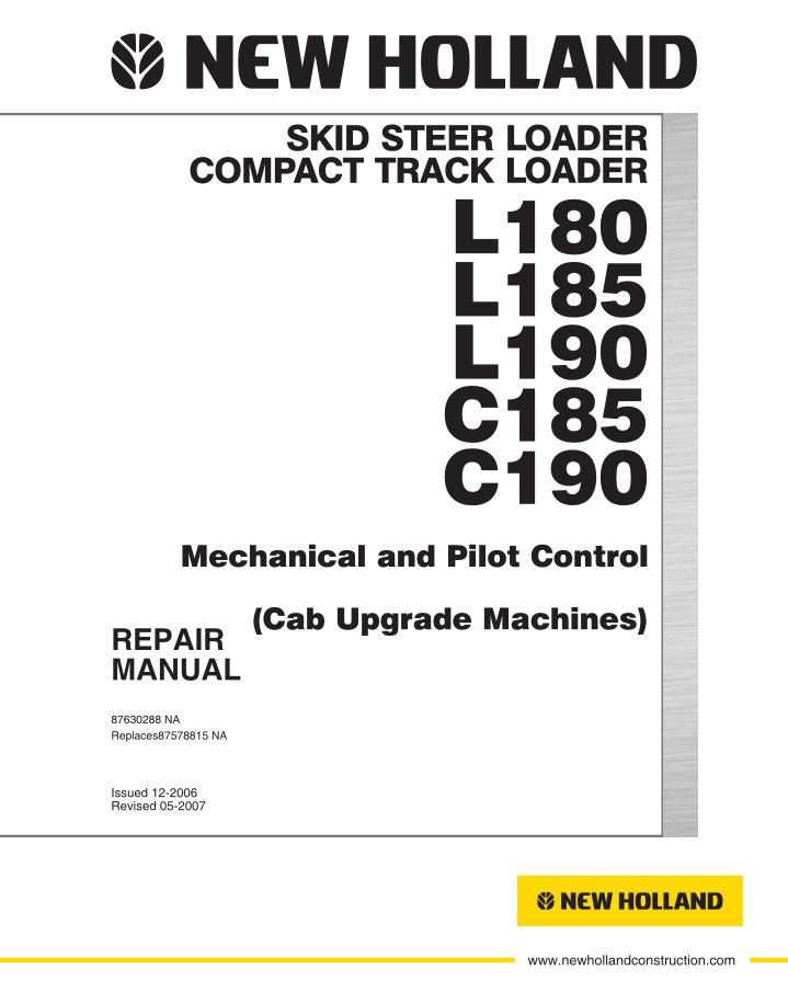
SKID STEER LOADER COMPACT TRACK LOADER L180 L185 L190 C185 C190 Mechanical and Pilot Control (Cab Upgrade Machines) REPAIR MANUAL 87630288 NA Replaces87578815 NA CNH AMERICA LLC North American English Issued 12-2006 245 E NORTH AVENUE Part Number 87630288 NA Revised 05-2007 CAROL STREAM, IL 60188 U.S.A. Printed in U.S.A. Bur NEW HOLLAND CONSTRUCTION IS A BRAND OF CNH. www.newhollandconstruction.com A GLOBAL LEADER FOR CONSTRUCTION EQUIPMENT, AGRICULTURE EQUIPMENT AND FINANCIAL SERVICES.
Copyright New Holland REPAIR MANUAL C185 C190 L180 L185 L190 87630288 1 6/6/2007
Copyright New Holland Contents INTRODUCTION DISTRIBUTION SYSTEMS A A.10.A PRIMARY HYDRAULIC POWER SYSTEM A.12.A SECONDARY HYDRAULIC POWER SYSTEM A.16.A HIGH FLOW HYDRAULIC POWER SYSTEM A.30.A ELECTRICAL POWER SYSTEM A.40.A LIGHTING SYSTEM POWER PRODUCTION B B.10.A ENGINE B.20.A FUEL AND INJECTION SYSTEM B.30.A AIR INTAKE SYSTEM B.50.A ENGINE COOLANT SYSTEM B.60.A LUBRICATION SYSTEM B.80.A STARTING SYSTEM POWER TRAIN C POWER COUPLING Fixed coupling C.10.B TRANSMISSION Hydrostatic C.20.F TRAVELLING D D.10.A FRONT AXLE REAR AXLE D.12.A D.20.F STEERING Steering clutch PARKING BRAKE Hydraulic D.32.C D.50.B WHEELS AND TRACKS Tracks WHEELS AND TRACKS Wheels D.50.C Final drive D.15.A BODY AND STRUCTURE E E.32.A USER CONTROLS AND SEAT E.34.A USER PLATFORM E.40.B ENVIRONMENT CONTROL Heating system 87630288 1 6/6/2007
https://www.ebooklibonline.com Hello dear friend! Thank you very much for reading. Enter the link into your browser. The full manual is available for immediate download. https://www.ebooklibonline.com
Copyright New Holland ENVIRONMENT CONTROL Air conditioning system E.40.C E.50.B SAFETY SECURITY ACCESSORIES Safety WORKING ARM H H.40.B SINGLE ARM Lift SINGLE ARM TOOL ATTACHMENT Tilt H.50.C TOOLS AND COUPLERS J J.50.B CARRYING Unarticulated tools COUPLING Hydraulic coupling J.80.C J.80.B COUPLING Mechanical coupling 87630288 1 6/6/2007
Copyright New Holland INTRODUCTION 87630288 1 6/6/2007 1
Copyright New Holland INTRODUCTION Basic instructions Technical Information This manual has been produced by a new technical information system. This new system is designed to deliver technical information electronically through CDROM and in paper manuals. A coding system called ICE has been developed to link the technical information to other Product Support functions e.g. Warranty. Technical information is written to support the maintenance and service of the functions or systems on a customers machine. When a customer has a concern on his machine it is usually because a function or system on his machine is not working at all, is not working efficiently, or is not responding correctly to his commands. When you refer to the technical information in this manual to resolve that customers concern, you will find all the information classified using the new ICE coding, according to the functions or systems on that machine. Once you have located the technical information for that function or system then you will find all the mechanical, electrical or hydraulic devices, compo nents, assemblies and sub assemblies for that function or system. You will also find all the types of information that have been written for that function or system, the technical data (specifications), the functional data (how it works), the diagnostic data (fault codes and troubleshooting) and the service data (remove, install adjust, etc.). By integrating this new ICE coding into technical information , you will be able to search and retrieve just the right piece of technical information you need to resolve that customers concern on his machine. This is made possible by attaching 3 categories to each piece of technical information during the authoring process. The first category is the Location, the second category is the Information Type and the third category is the Product: LOCATION is the component or function on the machine, that the piece of technical information is going to describe e.g. Fuel tank. INFORMATION TYPE is the piece of technical information that has been written for a particular component or function on the machine e.g. Capacity would be a type of Technical Data that would describe the amount of fuel held by the Fuel tank. PRODUCT is the model that the piece of technical information is written for. Every piece of technical information will have those 3 categories attached to it. You will be able to use any combination of those categories to find the right piece of technical information you need to resolve that customers concern on his machine. That information could be: the description of how to remove the cylinder head a table of specifications for a hydraulic pump a fault code a troubleshooting table a special tool How to Use this Manual This manual is divided into Sections. Each Section is then divided into Chapters. Contents pages are included at the beginning of the manual, then inside every Section and inside every Chapter. An alphabetical Index is included at the end of a Chapter. Page number references are included for every piece of technical information listed in the Chapter Contents or Chapter Index. Each Chapter is divided into four Information types: (D) Technical Data (specifications) for all the mechanical, electrical or hydraulic devices, components and, as semblies. (C) Functional Data (how it works) for all the mechanical, electrical or hydraulic devices, components and as semblies. (G) Diagnostic Data (fault codes, electrical and hydraulic troubleshooting) for all the mechanical, electrical or hydraulic devices, components and assemblies. 87630288 1 6/6/2007 3
Copyright New Holland INTRODUCTION (F) Service data (remove disassembly, assemble, install) for all the mechanical, electrical or hydraulic devices, components and assemblies. Sections Sections are grouped according to the main functions or a systems on the machine. Each Section is identified by a letter A, B, C etc. The amount of Sections included in the manual will depend on the type and function of the machine that the manual is written for. Each Section has a Contents page listed in alphabetic/numeric order. This table illustrates which Sections could be included in a manual for a particular product. SECTION A Distribution Systems B Power Production C Power Train D Travelling E Body and Structure F Frame Positioning G Tool Positioning H Working Arm J Tools and Couplers K Crop Processing L Field Processing PRODUCT Tractors Vehicles with working arms: backhoes, excavators, skid steers, ..... Combines, forage harvesters, balers, .... Seeding, planting, floating, spraying equipment, .... Mounted equipment and tools, ..... X X X X X X X X X X X X X X X X X X X X X X X X X X X X X X X X X X X X X X X X Chapters Each Chapter is identified by a letter and number combination e.g. Engine B.10.A The first letter is identical to the Section letter i.e. Chapter B.10 is inside Section B, Power Production. CONTENTS The Chapter Contents lists all the (D) technical data (specifications), (C) functional data (how it works), (F) service data (remove, install adjust, etc..) and (G) diagnostic data (fault codes and troubleshooting) that have been written in that Chapter for that function or system on the machine. Contents POWER PRODUCTION ENGINE _ 10.A TECHNICAL DATA ENGINE General specification (B.10.A D.40.A.10) FUNCTIONAL DATA 3 4 ENGINE Dynamic description (B.10.A C.30.A.10) SERVICE ENGINE Remove (B.10.A F.10.A.10) DIAGNOSTIC ENGINE Troubleshooting (B.10.A G.40.A.10) 5 6 INDEX The Chapter Index lists in alphabetical order all the types of information (called Information Units) that have been written in that Chapter for that function or system on the machine. 87630288 1 6/6/2007 4
Copyright New Holland INTRODUCTION Index POWER PRODUCTION B ENGINE 4 3 5 6 ENGINE Dynamic description (B.10.A C.30.A.10) ENGINE General specification (B.10.A D.40.A.10) ENGINE Remove (B.10.A F.10.A.10) ENGINE Troubleshooting (B.10.A G.40.A.10) Information Units and Information Search Each chapter is composed of information units. Each information unit has the ICE code shown in parentheses which indicates the function and the type of information written in that information unit. Each information unit has a page ref erence within that Chapter. The information units provide a quick and easy way to find just the right piece of technical information you are looking for. example information unit Information Unit ICE code ICE code classification Stack valve Sectional View (A.10.A.18 C.10.A.30) A 10.A Distribution systems hydraulic power 18 Stack valve 10.A.30 Sectional view C Functional data Primary 1 CRIL03J033E01 Navigate to the correct information unit you are searching for by identifying the function and information type from the ICE code. (1) Function and (2) Information type. (A) corresponds to the sections of the repair manual. (B) corresponds to the chapters of the repair manual. (C) corresponds to the type of information listed in the chapter contents, (D) Technical data, (C) Functional Data, (G) Diagnostic or (F) Service. (A) and (B) are also shown in the page numbering on the page footer. THE REST OF THE CODING IS NOT LISTED IN ALPHA NUMERIC ORDER IN THIS MANUAL. You will find a table of contents at the beginning and end of each section and chapter. You will find an alphabetical index at the end of each chapter. By referring to (A), (B) and (C) of the coding, you can follow the contents or index (page numbers) and quickly find the information you are looking for. 87630288 1 6/6/2007 5
Copyright New Holland INTRODUCTION Page Header and Footer The page header will contain the following references: Section and Chapter description The page footer will contain the following references: Publication number for that Manual, Section or Chapter. Version reference for that publication. Publication date Section, chapter and page reference e.g. A.10.A / 9 87630288 1 6/6/2007 6
Copyright New Holland REPAIR MANUAL DISTRIBUTION SYSTEMS C185 C190 L180 L185 L190 87630288 1 6/6/2007 A
Copyright New Holland DISTRIBUTION SYSTEMS PRIMARY HYDRAULIC POWER SYSTEM PRIMARY HYDRAULIC POWER SYSTEM Decontaminating 1. Start and run the engine at 1500 rpm (r/min). 2. Completelyretracttheallattachmentcylindersonthe machine. Stop the engine. WARNING If retracting the cylinder rods causes the attachment to be raised, block the attachment in place before pro ceeding to the next step. 39 4 3. Move each control lever in both directions to release pressure in the hydraulic circuits. 4. Loosen and remove the filler cap from the reservoir. 5. Drain the hydraulic oil from the reservoir. (A)Haveavailableacceptableequipmenttodrainthe hydraulic oil. (B) Remove the drain plug from the bottom of the reservoir. 6. Remove the hydraulic filter elementsfrom the ma chine. 7. Install new hydraulic filter elementson the machine. 8. Install the drain plug in the bottom of the reservoir. 9. Fill the hydraulic reservoir. (A.10.A) Reservoir Filling 10. Disconnect the line from the OPEN end and CLOSED end of each cylinder. 11. Be sure all control levers are in the NEUTRAL posi tion. 12. Start and run the engine at low idle. IMPORTANT: Check the oil level in the hydraulic reservoir frequently while doing step 13. Have another person hold a container under the hydraulic lines while you do step 13. 13. Slowly move the control lever for each bucket and lift cylinders in both directions until oil begins to flow from the open line. Hold the control lever in place until clean oil flows from the open line. 14. Stop the engine. 15. Connect the system line to the CLOSED end of each cylinder. 16. Connect a suitable drain line to the OPEN end of each cylinder and place the other end in an accept able container for contaminated oil. 17. Start the engine and run the engine at low idle. 18. Slowly and completely extend all cylinders. As the piston rod comes in/out of the cylinder, oil will be pushed out of the OPEN end of the cylinders. IMPORTANT: Any attachment or part of an attachment that is raised must be supported with acceptable equipment to prevent the attachment from falling. 87630288 1 6/6/2007 A.10.A / 31
Copyright New Holland DISTRIBUTION SYSTEMS PRIMARY HYDRAULIC POWER SYSTEM 19. Support any attachments that will be in the RAISED position. 20. Stop the engine. 21. Disconnect the drain lines and connect the system lines to the cylinders. 22. Check the oil level in the hydraulic reservoir. Add oil as required. 23. Install the filler cap on the reservoir. 24. Remove the hydraulic filter element from the ma chine. 25. Install a new hydraulic filter element on the machine. 26. Start and run the engine at 1500 rpm (r/min), oper ate each hydraulic circuit to completely extend and retract the cylinders. 27. Stop the engine and check for leaks. Check the oil level in the hydraulic reservoir. Add oil as required. Reservoir Filling (A.10.A) 87630288 1 6/6/2007 A.10.A / 32
Copyright New Holland DISTRIBUTION SYSTEMS PRIMARY HYDRAULIC POWER SYSTEM Relief valve Flow test 1. Park the machine on a level surface. loader bucket to the floor. Stop the engine. Lower the 2. Disconnect the hose from the fitting on the pressure port (1) of the hydraulic pump. Install a T fitting at the pressure port (1) on the hydraulic pump. Reconnect the pressure hose to one side of the T fitting. Con nect the flowmeter inlet hose to the remaining con nection on the T fitting. Place the flowmeter outlet hose into the reservoir. Secure the outlet hose to the reservoir so that the hose is submerged below the surface of the hydraulic oil. 1 bd05f004_4 3. Make sure that the oil level in the hydraulic reservoir is correct. 4. The oil must be at operating temperature. If the oil is not at operating temperature, run the engine at full throttle. Hold the auxiliary hydraulic flow control pedalintheONpositionandclosethepressurevalve of the flowmeter until the pressure gauge indicates 103 bar (1500 psi). Continue to run the engine at full throttle until the temperature of the oil is 52 C (125 F). 5. Continue to hold the auxiliary hydraulic flow control pedal in the ON position. Continue to run the engine at full throttle. Slowly close the pressure valve. As the pressure increases, the flow indication will de crease slowly. As you continue to close the pressure valve, you will reach a point at which the flow indica tion begins to decrease rapidly. This is the point at which the main relief valve starts to open. Read the pressure gauge and record the reading as test num ber 5. 6. Continue to close the pressure valve until the indi cation of the flow gauge is zero. This is the point at which the main relief valve is completely open. Read the pressure gauge and record the reading as test number 6. 7. Open the pressure valve completely. Decrease the engine speed to low idle and stop the engine. 8. Refer to specifications Relief valve General spec ification (A.10.A) Relief valve General specifica tion (A.10.A) If the pressure setting of the main re lief valve is not within the specifications, you must replace the main relief valve. 9. If you replaced the main relief valve, repeat steps 5 through 7. 87630288 1 6/6/2007 A.10.A / 33
Copyright New Holland DISTRIBUTION SYSTEMS PRIMARY HYDRAULIC POWER SYSTEM 10. If the completely open pressure (step 6) is as spec ified, but the pressure at which the main relief valve begins to open (step 5) is 205 bar (2975 psi) or less, the main relief valve is damaged and must be re placed before you do further testing. NOTE: Understanding the results of the tests are outlined in the steps below. 11. Refer to Hydraulic pump Flow test (A.10.A) Hy draulic pump Flow test (A.10.A) If the flow indica tion for a circuit was approximately the same as the flowindicationatthesamepressureinTestNumber1 of the Hydraulic Pump Flow Test , the circuit is good. 12. If the flow indication for a circuit was more than 3.8 L/min (one gpm) less than the flow indication at the same pressure in Hydraulic pump Flow test (A.10.A) Test Number 1, there is leakage in that circuit. 87630288 1 6/6/2007 A.10.A / 34
Copyright New Holland DISTRIBUTION SYSTEMS PRIMARY HYDRAULIC POWER SYSTEM Relief valve Pressure test CAS1808 NOTE: Flat face couplers are not included with the CAS 1808 Flowmeter Fitting Kit or the CAS 1804 Pressure Test Fitting Kit. 1. Park the machine on a level surface. Lower the loader bucket to the floor. 2. The oil must be at operating temperature. To heat the oil, do the following steps: A. With the engine running at full throttle, hold the bucket control lever in the ROLLBACK position for 10 seconds. B. Put the bucket control lever in the NEUTRAL po sition for 10 seconds. C. Repeat steps A and B until the temperature of the oil is 52 C (125 F) or the side of the reservoir is very warm. 3. Use a pressure gauge with a capacity of at least 276 bar (4000 psi). Connect the pressure gauge to one of the auxiliary hydraulic couplers on the left hand loader arm. 4. Run the engine at full throttle. iary hydraulic flow control pedal to pressurize the hy draulic line which has the pressure gauge. Record the indication on the pressure gauge. Then return the auxiliary hydraulic flow control pedal to the Neu tral position and decrease the engine speed to low idle. Stop the engine. Actuate the auxil 5. Compare the indication with the specification . Re lief valve General specification (A.10.A) If the in dication is not correct, replace the main relief valve. Then do the pressure check again to make sure that the setting is correct. 87630288 1 6/6/2007 A.10.A / 35
Copyright New Holland DISTRIBUTION SYSTEMS PRIMARY HYDRAULIC POWER SYSTEM Hydraulic pump Flow test NOTE: Two persons are required to perform the flowmeter tests for safety to avoid possible injury. One person must be seated in the operators seat when the engine is running. The second person is to control the flowmeter and take the readings. 1. Park the machine on a level surface. Lower the loader bucket to the floor. Stop the engine. 2. Disconnect the hose from the pump pressure port (1) at Test Point 1 . Install a plug in the hose. Connect the flowmeter inlet hose to the fitting at the pressure port (1) of the pump. 1 bd05f004_4 3. Puttheflowmeteroutlethoseintothehydraulicreser voir. Use wire to fasten the flowmeter outlet hose be low the surface of the hydraulic oil. 4. Make sure that the oil level in the hydraulic reservoir is correct. 5. Make sure that the pressure valve of the flowmeter is opened completely. 6. The oil must be at operating temperature. If the oil is not at operating temperature, run the engine at full throttle and close the pressure valve of the flowmeter untilthepressuregaugeindicates103bar(1500psi). Continue to run the engine at full throttle until the temperature of the oil is 52 C (125 F). Then open the pressure valve completely. 7. Make sure that the pressure valve is opened com pletely. Adjust the engine speed to 2300 r/min (rpm) and read the flow gauge. Read the flow and record the reading as test number 1 . 8. Slowly close the pressure valve on the flowmeter un til the pressure gauge indicates 97 bar (1400 psi). Keep the engine running at 2300 r/min (rpm). Read the flow and record the reading as test number 2 . 9. Slowly close the pressure valve on the flowmeter un til the pressure gauge indicates 124 bar (1800 psi). Keep the engine running at 2300 r/min (rpm). Read the flow and record the reading as test number 3. 10. Slowly close the pressure valve on the flowmeter un til the pressure gauge indicates 152 bar (2000 psi). Keep the engine running at 2300 r/min (rpm). Read the flow and record the reading as test number 4. 11. Open the pressure valve completely. Decrease the engine speed to low idle and stop the engine. NOTE: Understanding the results of the tests are outlined in the steps below. 87630288 1 6/6/2007 A.10.A / 36
Suggest: If the above button click is invalid. Please download this document first, and then click the above link to download the complete manual. Thank you so much for reading
Copyright New Holland DISTRIBUTION SYSTEMS PRIMARY HYDRAULIC POWER SYSTEM 12. If the output at minimum pressure was less than the specification for Gear Pump Flow to Loader (Ma chine in Neutral) refer to Hydraulic pump General specification (A.10.A), the problem can be a restric tion between the reservoir and the gear pump, or the problemcanbeabadlywornordamagedgearpump. 13. If the output at minimum pressure was more than the specification refer to Hydraulic pump General specification (A.10.A), there are no problems be tween the reservoir and the gear pump. However, the gear pump can be worn or damaged and still have good flow at minimum pressure. 14. Loss of output at 152 bar (2200 psi) indicates that the gear pump is worn or damaged. To determine the efficiency of the gear pump, divide the flow indi cation from test number 4 by the flow indication from test number 1. This answer multiplied by 100 is the percent efficiency of the gear pump. If the efficiency of the gear pump is less than 75%, repair or replace the gear pump. If the efficiency of the gear pump is more than 75%, the pump is good. 87630288 1 6/6/2007 A.10.A / 37
https://www.ebooklibonline.com Hello dear friend! Thank you very much for reading. Enter the link into your browser. The full manual is available for immediate download. https://www.ebooklibonline.com

