Non-Inverting Operational Amplifier Circuit Overview
Explore the non-inverting operational amplifier configuration, its advantages, and how to calculate the closed-loop voltage gain. Discover the concept of a voltage follower and its applications in circuit design.

Download Presentation

Please find below an Image/Link to download the presentation.
The content on the website is provided AS IS for your information and personal use only. It may not be sold, licensed, or shared on other websites without obtaining consent from the author. If you encounter any issues during the download, it is possible that the publisher has removed the file from their server.
You are allowed to download the files provided on this website for personal or commercial use, subject to the condition that they are used lawfully. All files are the property of their respective owners.
The content on the website is provided AS IS for your information and personal use only. It may not be sold, licensed, or shared on other websites without obtaining consent from the author.
E N D
Presentation Transcript
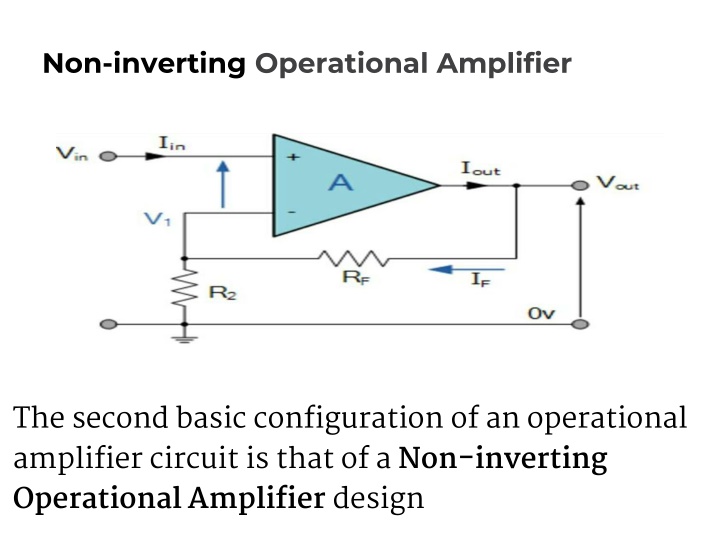
Non-inverting Operational Amplifier The second basic configuration of an operational amplifier circuit is that of a Non-inverting Operational Amplifier design
Non-inverting Operational Amplifier In this configuration, the input voltage signal, ( VIN) is applied directly to the non-inverting ( + ) input terminal which means that the output gain of the amplifier becomes Positive in value in contrast to the Inverting Amplifier circuit we saw in the last tutorial whose output gain is negative in value. The result of this is that the output signal is in-phase Feedback control of the non-inverting operational amplifier is achieved by applying a small part of the output voltage signal back to the inverting ( ) input terminal via a R R2 voltage divider network, again producing negative feedback. This closed-loop configuration produces a non-inverting amplifier circuit with very good stability, a very high input impedance, Rin approaching infinity, as no current flows into the positive input terminal, (ideal conditions) and a low output impedance, Rout as with the input signal. shown below.
Non-inverting Operational Amplifier In the previous Inverting Amplifier tutorial, we said that for an ideal op-amp No current flows into the input terminal of the amplifier and that V1 always equals V2 . This was because the junction of the input and feedback signal ( V1 ) are at the same potential
Equivalent Potential Divider Network Then using the formula to calculate the output voltage of a potential divider network, we can calculate the closed-loop voltage gain ( AV) of the Non-inverting Amplifier as follows:
Then the closed loop voltage gain of a Non-inverting Operational Amplifier will be given as: We can see from the equation above, that the overall closed-loop gain of a non-inverting amplifier will always be greater but never less than one (unity), it is positive in nature and is determined by the ratio of the values of R and R2.
Voltage Follower (Unity Gain Buffer) Voltage Follower (Unity Gain Buffer) If we made the feedback resistor, R equal to zero, (R = 0), and resistor R2 equal to infinity, (R2 = ), then the circuit would have a fixed gain of 1 as all the output voltage would be present on the inverting input terminal (negative feedback). This would then produce a special type of the non-inverting amplifier circuit called a Voltage Follower or also called a unity gain buffer . The advantage of the unity gain voltage follower is that it can be used when impedance matching or circuit isolation is more important than amplification as it maintains the signal voltage.
Non-inverting Voltage Follower In this non-inverting circuit configuration, the input impedance Rin has increased to infinity and the feedback impedance R reduced to zero. output is connected directly back to the negative inverting input so the feedback is 100% and Vin is exactly equal to Vout giving it a fixed gain of 1 or unity.


")