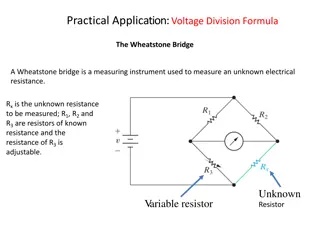
OPA2544 Bridge Circuit Stability Analysis and Design Considerations
"Learn about the OPA2544 bridge circuit stability analysis and design considerations for power op-amp circuits. Explore thermal design, power dissipation, electrical overstress, and more. Use resources for detailed design help and confirm stability with a PCB built design test." (Maximum characters: 500)

Download Presentation

Please find below an Image/Link to download the presentation.
The content on the website is provided AS IS for your information and personal use only. It may not be sold, licensed, or shared on other websites without obtaining consent from the author. If you encounter any issues during the download, it is possible that the publisher has removed the file from their server.
You are allowed to download the files provided on this website for personal or commercial use, subject to the condition that they are used lawfully. All files are the property of their respective owners.
The content on the website is provided AS IS for your information and personal use only. It may not be sold, licensed, or shared on other websites without obtaining consent from the author.
E N D
Presentation Transcript
OPA2544 Bridge Circuit Tim Green, MGTS Precision Op Amp Applications Manager January 10, 2018 1
Summary A) Power op amp circuits have several design considerations: 1) Thermal Design (heatsink, etc.) 2) Power Dissipation 3) Electrical Overstress from real world loads 4) Stability when driving cap loads 5) Small signal BW and slew rate limited large signal BW B) OPA2544 Bridge circuit is analyzed to drive 10uF to 100uF cap loads and be stable. Large signal slew rate limitations must be considered when trying to drive the load at frequency. Slew rate across the bridge tied load is doubled from the slew rate out of either op amp. If slewing fast into cap loads current requirements must be analyzed. For each op amp output: Slew Rate = 2*pi*f*Vout_peak. C) For more detailed design help use the resources sighted at the end of this presentation. D) This presentation focuses on stabilizing the op amps to drive 10uF to 100uF load. The resulting closed loop small signal BW = 1.4kHz. E) To minimize power dissipation use supplies as low as possible to yield maximum desired output swing. F) Final PCB built design should confirm stability by a closed loop, small signal, transient stability test. Note: All TINA-TI simulations can be run on the embedded schematics in this presentation by downloading the free TI SPICE simulator, TINA-TI, at: http://www.ti.com/tool/tina-ti 2
Final Circuit R4 200k Vs- 35 Vs+ 35 C9 470p Vs- Vs+ C6 100u C10 100u + + - - Z1 BZV55C36 Vs- Vs- D2 MUR840 C12 330n R6 4.64k C2 470n R3 66.5k AM1 - VF1 + + D1 MUR840 Vin 1 U1 OPA544 C1 470n C7 10n Vs+ R5 10 Vs+ Z2 BZV55C36 R2 30 C5 100u C11 470p R7 200k R8 200k Z3 BZV55C36 C13 330n R9 4.64k Vs- D4 MUR840 C4 470n Vs- - VF2 + + AM2 U2 OPA544 C8 10n R1 10 D3 MUR840 C3 470n Vs+ Vs+ Z4 BZV55C36 3
OPA2544 Bridge Circuit Stability Analysis 4
Master Loop No Comp Loaded Aol = Voa 1/Beta = Voa/VFB Loop Gain = VFB Master Op Amp Loop Gain Vs- 35 Vs+ 35 Vs- Vs+ VFB 1.579523uV R4 200k Cin 18p Vs- Vs- D2 MUR840 J1 J1 C11 1T Voa -3.007522V L1 1T R3 66.5k AM1 -200.516044mA - VF1 -3.007522V + VG1 + + D1 MUR840 U1 OPA544 Vin 1 C7 10n Vs+ R5 10 Vs+ R2 30 C5 100u R7 200k R8 200k Vs- D4 MUR840 Vs- - VF2 3.007508V + + AM2 200.501006mA U3 OPA544 C8 10n R1 10 D3 MUR840 Vs+ 5 Vs+
Master Loop No Comp, Modify 1/Beta for Stability 140 120 Loaded Aol Loaded Aol 10uF 10uF 100 Loaded Aol 100uF 100uF Loaded Aol 80 60 1/Beta 10uF & 100uF 10uF & 100uF 1/Beta Modify 1/Beta to stabilize both 10uF and 100uF Gain (dB) 40 20 0 fcl 100uF -20 -40 fcl 10uF -60 -80 1 10 100 1k 10k 100k 1M 10M 100M Frequency (Hz) 6
Master Loop Final Comp Loaded Aol = Voa 1/Beta = Voa/VFB Loop Gain = VFB Master Op Amp Loop Gain Vs- 35 Vs+ 35 Vs- Vs+ VFB 1.580078uV R4 200k C13 470p J1 C9 18p C11 1T Vs- Vs- D2 MUR840 + VG1 J1 Voa -3.007522V L1 1T R3 66.5k AM1 -200.516044mA - VF1 -3.007522V Vin 1 R9 4.64k + C12 330n + D1 MUR840 U1 OPA544 C7 10n Vs+ R5 10 Vs+ C5 10u R2 30 C14 470p R7 200k R8 200k Vs- D4 MUR840 R6 4.64k Vs- C15 330n - VF2 3.007508V + + AM2 200.501006mA U3 OPA544 C8 10n R1 10 D3 MUR840 Vs+ Vs+ Since Master and Slave Op Amp are symmetrical relative to cap load, we will compensate Slave the same as Master and check for loop gain stability on each. 7
Master Loop Final Comp Loop Gain Phase Margin (10uF) = 123 degrees Loop Gain Phase Margin (100uF) = 176 degrees 8
Slave Loop Final Comp Loaded Aol = Voa 1/Beta = Voa/VFB Loop Gain = VFB Slave Op Amp Loop Gain Vs- 35 Vs+ 35 Vs- Vs+ R4 200k C13 470p Vs- Vs- D2 MUR840 R3 66.5k AM1 -200.516044mA - VF1 -3.007522V Vin 1 R9 4.64k + C12 330n + D1 MUR840 U1 OPA544 C7 10n Vs+ R5 10 Vs+ R2 30 C5 10u C15 470p VFB -2.359898uV R7 200k R8 200k R6 4.64k C14 330n Vs- D4 MUR840 Vs- Cin 18p J1 J1 Voa 3.007508V L1 1T C11 1T - VF2 3.007508V + + + AM2 200.501006mA U3 OPA544 C8 10n VG1 R1 10 D3 MUR840 Vs+ Vs+ Since Master and Slave Op Amp are symmetrical relative to cap load, we will compensate Slave the same as Master and check for loop gain stability on each. 9
Slave Loop Final Comp Loop Gain Phase Margin (10uF) = 124 degrees Loop Gain Phase Margin (100uF) = 169 degrees 10
Closed Loop BW Vs- 35 Vs+ 35 Vs- Vs+ VFB -389.980594nV R4 200k C13 470p Vs- Vs- D2 MUR840 Voa_M -11.543411uV R3 66.5k Rcl1 1m AM1 -410.918857nA - VF1 -11.543uV R9 4.64k + + C12 330n + D1 MUR840 U1 OPA544 VG1 C7 10n Vs+ R5 10 Vs+ + R2 30 C5 100u V C14 470p VM1 -12.325893uV R7 200k R8 200k Voa_S 783.303573nV Vs- D4 MUR840 R6 4.64k Vs- C15 330n Rcl2 1m - VF2 782.89271nV + + AM2 410.863092nA U3 OPA544 C8 10n R1 10 D3 MUR840 Vs+ Vs+ 11
Closed Loop BW 20 10pF 10pF 0 10uF 10uF -20 100uF 100uF -40 -3dB: 10pF = 1.15kHz 10uF = 1.2kHz 100uF = 1.6kHz -60 Gain (dB) -80 -100 -120 -140 -160 -180 -200 180 10pF 10pF 135 90 Phase [deg] 45 0 100uF 100uF -45 -90 10uF 10uF -135 -180 1 10 100 1k 10k 100k 1M 10M 100M Frequency (Hz) 12
Key Design Resources https://e2e.ti.com/support/amplifiers/precision_amplifiers/w/design_notes Download all parts of the following presentations: 13 of 74