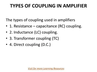
Operation in Serially Powered Environment: Communication and Coupling Concepts
In a serially powered environment, communication and coupling concepts play a crucial role in system operation. AC and DC coupling methods are explored for efficient data transmission between system components. The use of clock speeds, differential lines, and considerations for ground potentials are discussed. The feasibility of DC coupling, advantages over AC coupling, and implementation details are highlighted through various concepts in the context of ASIC and inter-chip links.

Download Presentation

Please find below an Image/Link to download the presentation.
The content on the website is provided AS IS for your information and personal use only. It may not be sold, licensed, or shared on other websites without obtaining consent from the author.If you encounter any issues during the download, it is possible that the publisher has removed the file from their server.
You are allowed to download the files provided on this website for personal or commercial use, subject to the condition that they are used lawfully. All files are the property of their respective owners.
The content on the website is provided AS IS for your information and personal use only. It may not be sold, licensed, or shared on other websites without obtaining consent from the author.
E N D
Presentation Transcript
Operation in Serially Powered Environment 1
Operation in Serially Powered Env. (1) Original concept: AC coupling comes naturally to mind, when system components seat on different common mode potentials Most likely, it will not be 40 MHz. 3 lines for communication SCL clock for slow control and system clock for MAPS lpGBT receives data from VTRx+ (2.56 Gbps), distributes them to eLink lines; 3 differential lines: CLK, SDA_in, SDA_out; question: CLK (fCLK of MOSAIX = 320 or 160 MHz) should slow control run at this speed? 2
Operation in Serially Powered Env. (2) Adjusted concept: DC coupling is possible when common mode voltage differ not much 320 MHz Higher speed clock elected by MOSAIX. Still 3 lines and SCL clock for slow control and system clock for MAPS 3
Operation in Serially Powered Env. (3) Ancillary ASIC seats between lpGBT and EIC LAS on OB staves and disks Serial Powering makes each EIC LAS seat on local ground (gnd1, gnd2, gnd3 ) Communication to and from lpGBT must take into account gnd1 4 potential differences into account Natural seems to use AC-coupling, but DC-coupling offers advantages for transmission: insensitive to position and number of taps from transmission line; transmission can be paused and restarted; no need of external capacitors; flexibility of configuration (length of chain); simpler system design. DC-coupling AC-coupling Is DC-coupling feasible? highest to lowest potential for positive charges 4
Operation in Serially Powered Env. (4) Yes, DC coupling is feasible with CML-like inter-chip TX-RX link ! serial powering current in shunt voltage >1.2V LDO voltage >=1.2V ground of 1st LAS ground of 2nd LAS ground of 3rd LAS ground of 4th LAS serial powering current out enabling elements for the design: small potential differences (X00 mV) between vdd and gnd of two neighboring AncASICs; selection of Partially Depleted SOI CMOS process comes with all transistors isolated and having their terminals hanging slightly below or protruding slightly above ground and power potential of predecessor and successor. cross-section of PDSOI process with selected metal stack option and featuring deep trench isolation DTI 5
Operation in Serially Powered Env. (5) comparison of DC and AC coupled link running at 160 Mbps driven by a pseudo-random stream of non-return- to-zero binary data 6
Operation in Serially Powered Env. (6) Transmitter: PMOS differential pair Zo= 100 (differential) IBias= 8 mA and output swing = 400 mVpp Receiver: NMOS differential pair Zo= 100 (differential) IBias= 50 A mA and rail to rail output restored 7
Operation in Serially Powered Env. (7) Data rate = 320 Mb/s, NRZ coding Simulated using a simple repeated 0/1 pattern VDD = 1.2 V Tx 1.2V Tx Rx 1.2V Rx Imprecision related to neglecting step of 0.3-0.5 V (TBD) from ground of previous power domain and 1.2V level of next one (irrelevant to generality) 8
Operation in Serially Powered Env. (8) Simulation: DC Simulation: DC- -coupled, daisy chain coupled, daisy chain CML TX/RX test structure3 CML TX/RX test structure2 CML TX/RX test structure1 1.2V 1.2V 1.2V D2 D3 D1 Din 1.2V 1.2V 1.2V PRBS7 Source Driver ASIC #2 ASIC #3 ASIC #1 9
Operation in Serially Powered Env. (8) Input-output transmission delay = 1.06 ns Level differences corrected for visualization 10
Operation in Serially Powered Env. (9) Layouts of CML TX/RX test structures Layouts of CML TX/RX test structures TX Wide metal traces used in the transmitter and the receiver input load to ensure compliance with electromigration rules RX 11

")
")
")
")
")
")
")
")
")
")