Optical Modulation Techniques in Communication Systems
Learn about direct and indirect modulation techniques in optical communication systems, including advantages, disadvantages, and common external modulators like Lithium niobate modulators. Explore the process of converting digital data into optical signals for efficient transmission over fiber optics.

Download Presentation

Please find below an Image/Link to download the presentation.
The content on the website is provided AS IS for your information and personal use only. It may not be sold, licensed, or shared on other websites without obtaining consent from the author. If you encounter any issues during the download, it is possible that the publisher has removed the file from their server.
You are allowed to download the files provided on this website for personal or commercial use, subject to the condition that they are used lawfully. All files are the property of their respective owners.
The content on the website is provided AS IS for your information and personal use only. It may not be sold, licensed, or shared on other websites without obtaining consent from the author.
E N D
Presentation Transcript
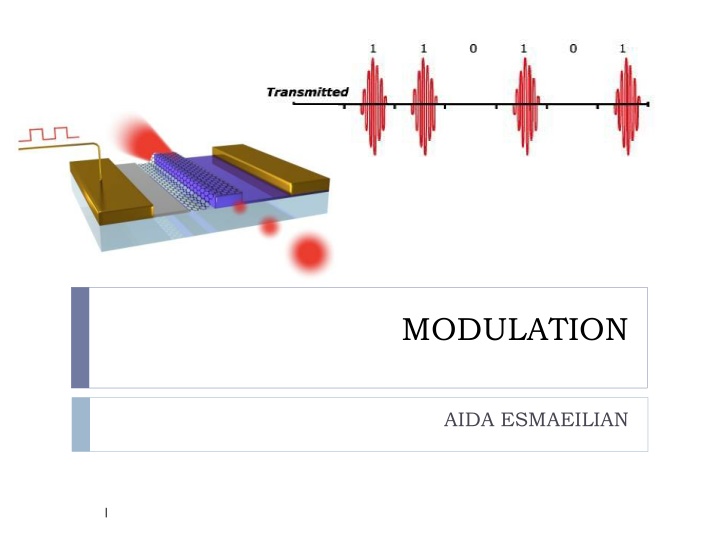
MODULATION AIDA ESMAEILIAN 1
MODULATION Modulation: the process of converting digital data in electronic form to an optical signal that can be transmitted over the fiber. Demodulation: the process of converting the optical signal back into electronic form and extracting the data that was transmitted. The ratio of the output powers for the 1 and 0 bits is called the extinction ratio 2
ook The most commonly used modulation scheme in optical communication is on-off keying (OOK) Bit rate 1Gb/s => bit interval 1 ns Bit interval 3
DIRECT MODULATION Advantage: simple and inexpensive, no other components are required. A major advantage of semiconductor lasers can be directly modulated. because of the long lifetime of the erbium atoms at the E2 level , erbium lasers cannot be directly modulated even at speeds of a few kilobits per second require an external modulator Disadvantage of direct modulation is that the resulting pulses are considerably chirped. Chirp is a phenomenon wherein the carrier frequency of the transmitted pulse varies with time, and it causes a broadening of the transmitted spectrum. 4
INDIRECT MODULATION External modulators in high-speed, dispersion-limited communication systems. (bit rate >= 10 Gb/s) OOK external modulator is placed in front of a light source and turns the light signal on or off based on the data to be transmitted External modulators become essential using solitons or return-to-zero (RZ) modulation practical RZ systems today use a continuous-wave DFB laser followed by a two-stage external modulator 5
Common external modulators 1- Lithium niobate modulators: By electro-optic effect, where an applied voltage induces a change in refractive index of the material. As a directional coupler or as a Mach-Zehnder interferometer (MZI) MZI offers a higher modulation speed for a given drive voltage and provides a higher extinction ratio 8
MZI Two titanium-diffused LiNbO3 waveguides form the two arms of a MZ interferometer In one state, the signals in the two arms of the MZI are in phase and interfere constructively and appear at the output. In the other state, applying a voltage causes a phase shift between the two arms of the MZI, leading to destructive interference and no output signal. 9
MZI Because the speed of light is altered by the application of a control voltage, electro-optic materials can be described as materials with a voltage-controlled index of refraction. Index of refraction = speed of light in vacuum / speed of light in material 10
MZI UI splits into two signals U1 and U2 at the first coupler. An electro-optic modulator, whose refractive index slightly varies as a function of applying voltage V, is embedded through one path. This affects on the relative phase shift of the two signals at the output couplers, where the two signals recombine. This variable phase shift changes the output signal UO. Therefore, UO can be varied by the voltage V 11
Common external modulators 2- Semiconductor electro-absorption (EA) modulators: Uses the same material and techniques used to fabricate semiconductor lasers allows an EA modulator to be integrated along with a DFB laser a very compact, lower-cost solution Its bandgap is higher than the photon energy of the incident light allows the light signal to propagate through. Applying an electric field to the modulator shrinking the bandgap of the material incident photons are absorbed Franz-Keldysh effect or the Stark effect chirp performance of EA is not as good as that of MZI 13
Subcarrier Modulation The data stream first modulates a microwave carrier, which, in turn, modulates the optical carrier Main carrier subcarrier 14
Optical Coupler A directional coupler is used to combine and split signals in an optical network Commonly made by fusing two fibers together in the middle: fused fiber couplers Also fabricated using waveguides in integrated optics P1 (1- )P2 P1 (1- )P1 P2 P2 : coupling ratio 15
Optical Coupler coupler can be wavelength selective: depends on the wavelength widely used to combine signals at 1310 nm and 1550 nm into a single fiber without loss: 1310 nm signal on input1 is passed through to output 1 1550 nm signal on input2 is passed through output 1 or wavelength independent (wavelength flat) over a usefully wide range: is independent of the wavelength L can be adjusted such that half the power from each input appears at each output: 3 dB coupler For monitoring purposes: couplers are called taps, designed typically 0.90 0.95 16
Optical Coupler Realization on planar waveguides or on optical fibers Fibers must be longitudinally fused so that the fields from the two branches interfere The length L of fusion is responsible for the coupling ratio http://www.fiber-patchcable.com/wp-content/uploads/2010/04/coupler.jpg 17
Isolator allows transmission in one direction but blocks all transmission in the other direction. Used at the output of optical amplifiers and lasers primarily to prevent reflections from entering these devices, which would otherwise degrade their performance Insertion loss: the loss in the forward direction, as small as possible Isolation: the loss in the reverse direction, as large as possible Typical insertion loss is around 1 dB, and the isolation is around 40 50 dB 18
Circulator Is similar to an isolator, except that it has multiple ports, typically three or four In a three-port circulator, an input signal on port 1 sent out on port 2, an input signal on port 2 sent out on port 3, an input signal on port 3 sent out on port 1. Circulators are useful to construct optical add/drop elements 19
Circulator http://www.thorlabs.us/images/TabImages/Circulator-2.jpg 20
Circulator http://www.thorlabs.us/images/TabImages/Circulator-1.jpg 21


