Optimization of HOM Heating in IR Region for CEPC Workshop
"Explore the optimization of HOM heating in the IR region for the CEPC workshop, focusing on beam parameters, position of the IR pipe, and power distribution. Dive into impedance results and power optimization for an efficient IR pipe model."

Download Presentation

Please find below an Image/Link to download the presentation.
The content on the website is provided AS IS for your information and personal use only. It may not be sold, licensed, or shared on other websites without obtaining consent from the author. If you encounter any issues during the download, it is possible that the publisher has removed the file from their server.
You are allowed to download the files provided on this website for personal or commercial use, subject to the condition that they are used lawfully. All files are the property of their respective owners.
The content on the website is provided AS IS for your information and personal use only. It may not be sold, licensed, or shared on other websites without obtaining consent from the author.
E N D
Presentation Transcript
HOM Heating in IR region of MDI for CEPC HOM Heating in IR region of MDI for CEPC Liu Yu dong, Shi Hao Yu, Bai Sha, Wang Hai Jing, Wang Na, Wang Dou CEPC MDI workshop, Heng Yang, March 29-31, 2023
outline outline Beam parameters from CDR to TDR for CEPC Position of IR pipe and HOM heating from CDR to TDR Optimization on IR pipe design for depression HOM power Impedance results and power distribution for optimized IR pipe model Summary
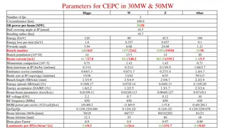
Beam parameters in different phase TDR 50MW CDR -----------------------------> TDR(30MW) ------------------------> ? ? Z 3T Z 2T ? ? W Higgs Z Higgs W W Higgs Z 2 Number of IPs Circumference (km) SR power per beam (MW) Half crossing angle at IP (mrad) Energy (GeV) Energy loss per turn (GeV) Number of IPs Beam energy (GeV) Circumference (km) Synchrotron radiation loss/turn (GeV) Crossing angle at IP (mrad) Piwinski angle 2 2 Number of IPs 120 80 45.5 100.0 30 16.5 100.0 Circumference (km) 100 50 SR power per beam (MW) 1.73 0.34 0.036 16.5 Half crossing angle at IP (mrad) 45.5 0.037 120 1.8 80 180 9.1 120 45.5 80 180 Energy (GeV) 16.5 2 0.357 0.037 1.8 9.1 Energy loss per turn (GeV) 0.357 3.48 7.0 23.8 44.6/44.6/22. 3 Damping time x/ y/ z (ms) 816/816/408 13.2/13.2/6.6 150/150/75 44.6/44.6/22.3 816/816/408 150/150/75 13.2/13.2/6.6 Damping time tx/ty/tz(ms) Number of particles/bunch Ne(1010) 15.0 12.0 8.0 29.52 Piwinski angle 4.88 5.98 1.23 24.23 11934 4.88 268 1.23 35 Piwinski angle Bunch number 5.98 1297 Bunch number Bunch spacing (ns) Beam current (mA) 242 680 17.4 1524 210 87.9 12000 (10% gap) 25 461.0 13104 446 58 Bunch number 2162 23 355 2714 (53% gap) 23 591 4524 (53% gap) Bunch spacing (ns) 154 Bunch spacing (ns) 257 (18% gap) (53% gap) (10% gap) (53% gap) Synchrotron radiation power (MW) 30 30 16.5 Bunch population (1011) Beam current (mA) Phase advance of arc FODO ( ) Momentum compaction (10-5) Beta functions at IP x*/ y* (m/mm) Emittance x/ y(nm/pm) Betatron tune nx/ny Beam size at IP sx /sy(um/nm) 1.4 803.5 60 1.43 1.3 16.7 90 0.71 2.0 3.3 90 0.71 1.35 84.1 60 1.43 Bunch population (1011) 1.3 2.14 2.0 1.35 Momentum compaction (10-5) function at IP x* / y* (m) Emittance x/y (nm) Beam-beam parameters x/ y RF voltage VRF (GV) RF frequency fRF(MHz) Harmonic number Natural bunch length sz(mm) Bunch length sz(mm) 1.11 1340.9 27.8 5.5 Beam current (mA) Phase advance of arc FODO ( ) 140.2 0.36/0.0015 1.21/0.0024 0.018/0.109 2.17 0.36/0.0015 0.54/0.0016 0.013/0.123 0.47 0.2/0.0015 0.18/0.004 0.004/0.06 0.2/0.001 0.18/0.0016 0.004/0.079 0.10 60 90 90 60 Momentum compaction (10-5) 1.43 0.71 1.43 0.71 Beta functions at IP b x*/b y* (m/mm) 0.13/0.9 0.3/1 1.04/2.7 0.21/1 0.13/0.9 0.3/1 1.04/2.7 0.21/1 650 216816 0.27/1.4 266/267 6/35 0.64/1.3 445/445 14/36 1.4/4.7 445/445 39/113 0.87/1.7 266/266 13/42 0.64/1.3 0.27/1.4 1.4/4.7 Emittance ex/ey(nm/pm) Betatrontune nx/ny Beam size at IP sx/sy(um/nm) Bunch length (natural/total) (mm) 0.87/1.7 2.72 4.4 2.98 5.9 2.42 8.5 445/445 266/267 445/445 266/266 6/35 14/36 39/113 13/42 2.5/8.7 2.3/4.1 2.2/2.9 Bunch length (natural/total) (mm) 2.5/4.9 46.5/46.5/2 3.5 -468/-1161 156.4/156.4/74. 5 -468/-1161 2.3/4.1 2.2/2.9 2.7/10.6 2.5/4.9 Damping time tx/ty/tE(ms) 849.5/849.5/425.0 0.10/0.17 0.04/0.15 0.15/0.20 Energy spread (natural/total) (%) 0.07/0.14 0.04/0.13 0.10/0.17 0.15/0.20 Energy spread (natural/total) (%) 0.07/0.14 -513/-1594 Natural Chromaticity Betatron tune x/ y Synchrotron tune s Natural energy spread (%) Energy spread (%) -491/-1161 1.3/1.5 1.6/2.2 2.0/2.6 Energy acceptance (DA/RF) (%) 1.2/2.5 363.10 / 365.22 0.040 0.066 0.098 1.6/2.2 0.015/0.11 2.2 1.3/1.7 0.004/0.127 0.12 2.0/2.6 0.071/0.1 10 Energy acceptance (DA/RF) (%) Beam-beam parameters xx/xy RF voltage (GV) RF frequency (MHz) Longitudinal tune ns Beam lifetime (Bhabha/beamstrahlung) (min) 1.2/2.5 0.012/0.113 0.7 650 0.062 0.015/0.11 0.0045/0.13 0.071/0.1 Beam-beam parameters xx/xy RF voltage (GV) 0.012/0.113 0.065 0.100 0.134 0.028 0.038 0.080 2.2 10 0.1 0.7 650 RF frequency (MHz) 0.032 Longitudinal tune ns 0.049 0.078 0.062 Energy acceptance requirement (%) 1.35 0.90 0.49 0.035 0.049 0.078 Beam lifetime (Bhabha/beamstrahlung) (min) Beamstruhlung lifetime /quantum lifetime* (min) Lifetime (hour) F (hour glass) Luminosity/IP (1034cm-2s-1) With increasement on SR power, beam current, bunch number and population, the luminosity growth is achieved obviously. Luminosity Higgs& 2.93->5.0->8.3(almost 3 times); Z& 32.1->115->192( 6 times); W&10.1->16->26.7( 2.6 times) 39/40 81/23 86/400 60/700 80/18000 39/40 81/23 60/700 80/80 >400 80/18000 71 20 18 Beam lifetime (min) 55 80 0.97 115 20 0.9 5.0 18 0.89 0.5 Beam lifetime (min) Hourglass Factor Luminosity per IP (1034cm 2s 1) 55 0.9 16 2.5 0.43 0.89 2.93 1.4 0.94 10.1 4.6 0.97 0.9 0.89 Hourglass Factor 0.9 0.99 16.6 32.1 Luminosity per IP (1034cm 2s 1) 192 8.3 0.8 26.7
Position of IR pipe and HOM heating from CDR to TDR CDR central aperture beryllium pipe 28mm ->crotch->beam pipe (first quadrupole Q1A 28mm) ; MDI region length: 2.2m 28mm Simulation model P=283W (CDR beam parameters, Z mode& z~5mm) 28mm 28mm TDR (a) Almost doubled bunch current and beam current; (b) Shrunk beam pipe aperture ( 20mm, first quadrupole Q1A 20mm) 20mm 28mm HOM trapped in the IR pipe and the power heating 10 times higher at least 20mm The Critical problem: HOM heating in IR
Optimization on IR pipe design Primary structure X X Beam pipe: 28mm->20mm Shrink beam pipe:11mm Be 28mm Beam : 28mm Be 28mm Beam pipe: 20mm Be 28mm Beam pipe: 11mm P:5.76kw P:31.9kw Crotch Optimization: shape; slope X X X Crotch aperture: 46mm->40mm P:5.2kw Avoid any secondary photons into the IR Be 28mm Beam pipe: 20mm Be 28mm Beam pipe: 20mm X P:4.6kw P:3.98kw Approach for HOM reduction P:4.1kw X 1 Enlarge the aperture of beam pipe(>28mm) X 2 Installation HOM Absorber with ability 4kw(30MW) even 7kw(50MW) 3 shrink the central aperture to 20mm.
Optimization on IR pipe design(central aperture 20mm) Transition region: Round z=5mm: Two beam in the IR Loss factor Trap in IR @k_trap: 0.1v/pc Ptrap: H/W/Z/tt: 74.4w/363.1w/3597.2w/20.67w
Transition region: Round (including materials)& power distribution z=5mm: Two beam in the IR Loss factor Trap in IR @k_trap: 0.114v/pc Ptrap: H/W/Z/tt: 84.78w/413.6w/4097.23w/23.54w Position Start-end mm ttbar & (w/cm2) w Length (mm) Higgs(w) & (w/cm2) W (w) & (w/cm2) Z(w) Position material & (w/cm2) Be pipe (w) 0-85 Be 85 3.99 & 0.075 19.72 & 0.369 195.16 & 3.65 1.10 & 0.021 Be pipe transition(w) 85-130 Al 45 2.17 & 0.077 10.41 & 0.368 103.34 & 3.66 0.61 & 0.021 Transition pipe (w) 130-655 Al 525 24.90 & 0.055 121.70 & 0.268 1205.51 & 2.66 6.91 & 0.015 Transition w 655-700 Al 45 2.17 & 0.044 10.41 &0.210 103.34 & 2.09 0.61 & 0.012 RVC bellow w 700-780 Cu 80 1.85 & 0.021 8.93 & 0.102 88.24 &1.00 0.50 & 0.006 Transition on Y-crotch 780-805 Cu 25 0.57 & 0.02 2.77 & 0.095 27.61 & 0.95 0.18 & 0.006 Y- crotch (w) 805-855 Cu 50 1.18 &0.016 5.55 & 0.076 55.15 & 0.75 0.32 & 0.004 Quadrupole pipe(w) 855-1100 Cu 245 5.59 & 0.017 27.30 & 0.085 270.33 & 0.84 1.53 & 0.005 Total 0-1100 - 1100 42.39 &0.039 206.80 & 0.189 2048.69 & 1.87 11.76 & 0.011
Transition region: Racetrack Transition region: Round z=5mm: Two beam in the IR Loss factor Trap in IR @k_trap: 0.032v/pc Ptrap: H/W/Z/tt: 23.8w/116.1w/1150.1w/6.61w
Transition region: Racetrack (including materials)& power distribution z=5mm: Two beam in the IR Loss factor Trap in IR @k_trap: 0.032v/pc Ptrap: H/W/Z/tt: 23.8w/116.1w/1150.1w/6.61w Position Start-end mm ttbar & (w/cm2) w Length (mm) Higgs(w) & (w/cm2) W (w) & (w/cm2) Z(w) Position material & (w/cm2) Be pipe (w) 0-85 Be 85 1.12 & 0.02 5.535 & 0.104 54.781 & 1.02 0.31 & 0.005 Be pipe transition(w) 85-130 Al 45 0.61 & 0.02 2.923 & 0.104 29.008 & 1.02 0.17 & 0.007 Transition pipe (w) 130-655 Al 525 6.99 & 0.017 34.16 & 0.085 338.39 & 0.83 1.94 & 0.005 Transition w 655-700 Al 45 0.61 & 0.014 2.923 & 0.069 29.008 & 0.69 0.17 & 0.003 RVC bellow w 700-780 Cu 80 0.52 & 0.007 2.508 & 0.035 24.77 & 0.33 0.14 & 0.002 Transition on Y-crotch 780-805 Cu 25 0.16 & 0.007 0.778 & 0.031 7.7492 & 0.31 0.05 & 0.002 Y- crotch (w) 805-855 Cu 50 0.33 & 0.005 1.557 & 0.024 15.481 & 0.24 0.09 & 0.002 Quadrupole pipe(w) 855-1100 Cu 245 1.57 & 0.005 7.663 & 0.024 75.883 & 0.24 0.43 & 0.002 Total 0-1100 - 1100 11.9 & 0.012 58.05 & 0.057 575.07 & 0.57 3.3 & 0.003
Transition region: Racetrackupdated to 180mm z=5mm: Two beam in the IR Loss factor Trap in IR @k_trap: 0.0323v/pc Ptrap: H/W/Z/tt: 24.0w/117.1w/1160.8w/6.67w Position Start-end mm ttbar & (w/cm2) w Length (mm) Higgs(w) & (w/cm2) Z(w) W (w) & (w/cm2) Position material & (w/cm2) Be pipe (w) 0-85 Be 85 1.13 & 0.021 55.295 & 1.35 5.587 & 0.105 0.31 & 0.005 Be pipe transition(w) 85-180 Al 95 0.61 & 0.01 29.280 & 0.491 2.950 & 0.049 0.172 & 0.007 Transition pipe (w) 180-655 Al 475 6.99 & 0.017 341.562 & 0.83 34.48 & 0.085 1.958 & 0.005 Transition w 655-700 Al 45 0.62 & 0.015 29.28 & 0.701 2.95 & 0.071 0.172 & 0.004 RVC bellow w 700-780 Cu 80 0.52 & 0.007 25.002 & 0.337 2.532 & 0.034 0.14 & 0.002 Transition on Y-crotch 780-805 Cu 25 0.16 & 0.007 7.822 & 0.316 0.785 & 0.032 0.05 & 0.002 Y- crotch (w) 805-855 Cu 50 0.33 & 0.005 15.626 & 0.241 1.572 & 0.024 0.091 & 0.002 Quadrupole pipe(w) 855-1100 Cu 245 1.58 & 0.005 75.594& 0.24 7.735 & 0.024 0.434 & 0.002 Total 0-1100 - 1100 12.0 &0.011 580.46 & 0.56 58.594 &0.056 3.331 & 0.003
Power distribution with TDR50MW Position Start-end mm ttbar & (w/cm2) w Length (mm) Higgs(w) & (w/cm2) Z(w) W (w) & (w/cm2) Position material & (w/cm2) Be pipe (w) 0-85 Be 85 1.88 & 0.035 215.6 & 5.26 9.30 & 0.175 0.52 & 0.008 Be pipe transition(w) 85-180 Al 95 1.01 & 0.016 114.17 & 1.91 4.91 & 0.049 0.286 & 0.011 Transition pipe (w) 180-655 Al 475 11.63 & 0.028 1331.8 & 3.23 57.39 & 0.141 3.263 & 0.008 Transition w 655-700 Al 45 1.03 & 0.025 114.17& 2.73 4.91 & 0.118 0.286 & 0.007 RVC bellow w 700-780 Cu 80 0.86 & 0.012 97.49& 1.314 4.21 & 0.0565 0.233 & 0.003 Transition on Y-crotch 780-805 Cu 25 0.26 & 0.012 30.5 & 1.23 1.31& 0.0532 0.083 & 0.003 Y- crotch (w) 805-855 Cu 50 0.54 & 0.008 60.93& 0.94 2.62 & 0.04 0.151 & 0.003 Quadrupole pipe(w) 855-1100 Cu 245 2.63 & 0.008 294.76& 0.94 12.88 & 0.04 0.723 & 0.003 Total 0-1100 - 1100 19.97 &0.018 2263.3 & 2.18 97.53 &0.0932 5.551 & 0.005
Summary TDR CDR MDI pipe 28mm->20mm) 20mm -> TDR 30MW) TDR 50MW Thanks for your attention!


")
& power")

& power")
")
")