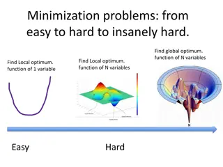
Explore the optimization of Luminosity (L) with SB2009 for Beam Delivery Systems (BDS) and working groups like LCWS 2010 and ILC 2010. Learn about the proposed reduction in beam power and strategies to recover luminosity effectively. Discover the Travelling Focus scheme to control the longitudinal focusing of opposing bunches for enhanced luminosity.
Please find below an Image/Link to download the presentation.
The content on the website is provided AS IS for your information and personal use only. It may not be sold, licensed, or shared on other websites without obtaining consent from the author. If you encounter any issues during the download, it is possible that the publisher has removed the file from their server.
You are allowed to download the files provided on this website for personal or commercial use, subject to the condition that they are used lawfully. All files are the property of their respective owners.
The content on the website is provided AS IS for your information and personal use only. It may not be sold, licensed, or shared on other websites without obtaining consent from the author.
E N D
Presentation Transcript
Optimization of L(E) with SB2009 Andrei Seryi, for BDS and other working groups LCWS 2010 / ILC 2010 March 28, 2010
Reduced beam-power parameters The proposed reduction in the beam power (number of bunches per pulse) requires us to squeeze the beam-beam parameters to compensate the nominal factor-of-two reduction in luminosity. SB2009 explores two possibilities: Pushing the beam-beam parameters into a high-disruption regime close to the single-beam kink-instability limits, at the expense of higher beamstrahlung and tighter collision tolerances. The proposed parameters could in principle recover the nominal RDR luminosity to within 25% (1.5 1034cm-2s-1). Making use of the so-called Travelling Focus [V.Balakin, LC91] effect, which can recover the remaining 25% luminosity without a further increase in the beamstrahlung. This approach comes at the cost of a very high disruption parameter, and the need for additional hardware A. Seryi, BDS: 2 ILC 2010, Mar/27/10
RDR parameter plane ranges compared to SB2009 RDR nominal SB2009 min max no TF with TF x 1010 1 2 2 2 2 Bunch population Number of bunches Linac bunch interval RM bunch length Normalized horizontal emittance at IP Normalized vertical emittance at IP Horizontal beta function at IP Vertical beta function at IP RMS horizontal beam size at IP RMS vertical beam size at IP Vertical disruption parameter Fractional RMS energy loss to beamstrahlung 1260 180 200 10 0.02 10 0.2 474 3.5 14 1.7 2625 369 300 10 0.04 20 0.4 640 5.7 19.4 2.4 5340 500 500 12 0.08 20 0.6 640 9.9 26.1 5.5 1312 530 300 10 0.035 11 0.48 470 5.8 25 4 1312 530 300 10 0.035 11 0.2 470 3.8 38 3.6 ns mm mm-mr mm-mr mm mm nm nm % x 1034cm-2s-1 2 1.5 2 Luminosity A. Seryi, BDS: 3 ILC 2010, Mar/27/10
Travelling Focus Scheme The travelling focus is a technique in which the focussing of opposing bunches is longitudinally controlled so as to defeat the hourglass effect and to restore the luminosity. The matched focusing condition is provided by a dynamic shift of the focal point to coincide with the head of the opposing bunch. The longer bunch helps to reduce the beamstrahlung effect and improvement of background conditions is expected. TF can be created in two ways Method 1 is to have small (uncompensated) chromaticity and coherent E-z energy shift dE/dz along the bunch. The required energy shift in this case is a fraction of a percent. Method 2 is to use a transverse deflecting cavity giving a z-x correlation in one of the Final Focus sextupoles and thus a z-correlated focusing. The needed strength of the travelling focus transverse cavity was estimated to be about 20% of the nominal crab cavity A. Seryi, BDS: 4 ILC 2010, Mar/27/10
R&D and Design Work for TDP2 The more demanding beam-beam parameters associated with SB2009 force us to be in a regime of higher disruption. Although there appears to be no fundamental show stoppers, a comprehensive study involving simulations is still required in an attempt to quantify the performance. Specifically: The higher disruption results in a higher sensitivity to any beam-beam offset. Thus, operation of the intra-train feedback and intra-train luminosity optimisation becomes more important and more challenging than in the case of RDR. Early estimates suggest that in order to contain the luminosity loss within 5%, a bunch-to- bunch jitter in the train needs to be less than 0.2nm at the IP (~5% of a nominal beam sigma). The parameter sets also have twice as small vertical betatron functions at the IP, which imply either tighter collimation, with gaps 40% closer to the beam core. This has implications for wakefields (emittance preservation) and fast feedback systems. Enhanced beam-halo loss in the tighter collimation could potentially increase the number of generated muons and hence the muon shielding requirements. A. Seryi, BDS: 6 ILC 2010, Mar/27/10
Low P Parameter Set with Traveling Focus Higher Disruption Higher sensitivity to y Intratrain Feedback more challenging Vertical bunch-bunch jitter to be <200pm for <5% lumi loss However, twice longer bunch separation will help to improve bunch-bunch uniformity & jitter x(LP)~50% x(RDR) y(LP-TF)~50% y(RDR) Collimation depth 1.4x deeper (smaller apertures) May have more muons however, have space to lengthen muon walls if needed A. Seryi, BDS: 7 ILC 2010, Mar/27/10
L(E) dependence in SB2009 Factor determine shape of L(E) in SB2009 Lower rep ( /2) rate below ~125GeV/beam Tighter focusing at IP => reduced collimation depth at lower E => increased beam degradation due to collimation wakes and due to limit (in X) on collimation depth A. Seryi, BDS: 9 ILC 2010, Mar/27/10
SB2009 Lumi L,E34 1/E Reduced e+ charge or reduced rate at IP 0.5/E 0.5/E Actual luminosity 0.25/E E CM A. Seryi, BDS: 11 ILC 2010, Mar/27/10
SB2009 Lumi L,E34 1/E Reduced e+ charge or reduced rate at IP 0.5/E 0.5/E Actual luminosity Recover L due to tighter focusing & TF Degradation due to collimation depth 0.25/E E CM A. Seryi, BDS: 12 ILC 2010, Mar/27/10
Possible mitigations of L(E) with SB2009 Consider doubling the rep rate at lower energy (say below ~125GeV/beam) Need to study implications for DR Sources Linac, HLRF, Cryogenics Consider FD optimized for ~250GeV CM May require change of FD to go to nominal 500GeV CM Or a more universal FD? (New design. Feasibility?) Shorter FD reduce beam size in FD and increase collimation depth, reducing collimation related beam degradation A. Seryi, BDS: 13 ILC 2010, Mar/27/10
DR High Repetition Rate S. Guiducci (LNF) ILC10, Beijing 27 March 2010 Global Design Effort A. Seryi, BDS: 14 ILC 2010, Mar/27/10
Emittance damping S. Guiducci (LNF) 1,00E-06 t/ x 0 2 4 6 8 10 1,00E-07 1,00E-08 epsyf epsxf 1,00E-09 1,00E-10 1,00E-11 1,00E-12 8 damping times are needed for the vertical emittance x = 26 ms 10 Hz x = 13 ms 5 Hz A. Seryi, BDS: 15 ILC 2010, Mar/27/10
Cost related modifications S. Guiducci (LNF) N. of RF cavities 8 16 Wiggler field 1.6 2.4 T Wiggler period 0.4 0.28 m A. Seryi, BDS: 17 ILC 2010, Mar/27/10
Sources implications Electron Source: doubling rep rate is not critical [Axel Brachmann, Tsunehiko Omori] Positron Source: The most important consequence of the increased rep rate will be the increased average power on the positron target There is a hope that it can be managed, but need more detailed studies [Jim Clarke, Wei Gai] A. Seryi, BDS: 18 ILC 2010, Mar/27/10
Linac and double rep rate Will have joint session with Linac colleagues this afternoon Will discuss Linac, HLRF, Cryogenics ( and also Injector 5 GeV linac Warm e+ capture linac ) A. Seryi, BDS: 19 ILC 2010, Mar/27/10
FD & collimation L*=3.5m, colldepthX=12, colldepthY=100 Reduced Collimation depth at lower E is responsible for large fraction of reduction of luminosity (w.r.to 1/E ideal curve) Shorter, matched to lower E, final doublet, will give some reduction of beam size at IP, thus increase the collimation depth mm X Y z, m L*=7.0m, colldepthX=10, colldepthY=60 y, mm mm QD0 VX QD0 QF1 VX EXT EXT z, m z, m Rays show trajectories of possible SR photons. Amount of rays is not quantitative. A. Seryi, BDS: 20 ILC 2010, Mar/27/10
FD for 1/2E & SR FD optimized for lower energy will allow increasing the collimation depth by ~10% in Y and by ~30% in X (Very tentative!) A. Seryi, BDS: 23 ILC 2010, Mar/27/10
ILC Final Doublet layout Should we have a separate FD optimized for lower E, and then exchange it? Or, can we build a universal FD, that can be reconfigured for lower E config? To be studied A. Seryi, BDS: 24 ILC 2010, Mar/27/10
Beam Parameters & mitigation Tentative! At 250 GeV CM the mitigations may give * 2 L due to double rep rate * about 1.4 L due to FD optimized for low E 25 A. Seryi, BDS: 25 ILC 2010, Mar/27/10
SB2009 Lumi L,E34 1/E 0.5/E Actual luminosity Possible luminosity (tentative!) E CM A. Seryi, BDS: 26 ILC 2010, Mar/27/10
Summary There are ways to increase L at low E which look promising and can be studied further A. Seryi, BDS: 27 ILC 2010, Mar/27/10


 with")


 dependence in SB2009")


 with SB2009")