Enhance the orthogonality of spatial streams in Uplink MU-MIMO for IEEE 802.11-15 through innovative masking and coding techniques. Explore the challenges, solutions, and simulation results to improve efficiency and performance in wireless communication systems.
Please find below an Image/Link to download the presentation.
The content on the website is provided AS IS for your information and personal use only. It may not be sold, licensed, or shared on other websites without obtaining consent from the author. If you encounter any issues during the download, it is possible that the publisher has removed the file from their server.
You are allowed to download the files provided on this website for personal or commercial use, subject to the condition that they are used lawfully. All files are the property of their respective owners.
The content on the website is provided AS IS for your information and personal use only. It may not be sold, licensed, or shared on other websites without obtaining consent from the author.
E N D
Presentation Transcript
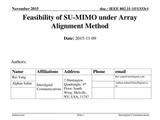
September 2015 doc.: IEEE 802.11-15/1088r0 LTF Design for Uplink MU-MIMO Date: 2015-09-14 Authors: Name Affiliations Address Phone email Daewon Lee Newracom 9008 Research Dr., Irvine, CA 92618 9008 Research Dr., Irvine, CA 92618 9008 Research Dr., Irvine, CA 92618 9008 Research Dr., Irvine, CA 92618 daewon.lee at newracom.com aiden.m at newracom.com Sungho Moon Newracom Yujin Noh Newracom yujin.noh at newracom.com minho.cheong at newracom.com heejung at yu.ac.kr Minho Cheong Newracom Heejung Yu Yeungnam Univ./ Newracom Submission Slide 1 Daewon Lee, Newracom
September 2015 doc.: IEEE 802.11-15/1088r0 Introduction LTF Sequence masking with orthogonal codes was proposed for Uplink MU-MIMO operation in [1]. Issues with LTF sequence masking with orthogonal codes were identified in [2]. This contribution presents further simulation results and an alternative method on obtaining orthogonality between spatial stream for frequency and phase offset compensation Submission Slide 2 Daewon Lee, Newracom
September 2015 doc.: IEEE 802.11-15/1088r0 Per-Stream Orthogonality using P-matrix P matrix masking Proposal in [1] obtains per-stream pseudo-orthogonality by masking P-matrix in the frequency domain. [ 1 ej2 ej2 2 ej2 3 ej2 4 ej2 5 ej2 6 ej2 7 ] CSD for SS #m x [ 1 1 -1 1 ][ 1 1 -1 1 ] x Row m of P matrix Orthogonal Code L1 L2 L3 L4 L5 L6 L7 L8 LTF sequence Final Output Sequence Submission Slide 3 Daewon Lee, Newracom
September 2015 doc.: IEEE 802.11-15/1088r0 Per-Stream Orthogonality using CSD Orthogonality CSD Interestingly, per-stream orthogonality can be also obtain without P-matrix masking, if the CSD is orthogonal between streams. Orthogonal Code [ 1 ej2 ej2 2 ej2 3 ej2 4 ej2 5 ej2 6 ej2 7 ] CSD for SS #m x No P-matrix Masking x L1 L2 L3 L4 L5 L6 L7 L8 LTF sequence Final Output Sequence Submission Slide 4 Daewon Lee, Newracom
September 2015 doc.: IEEE 802.11-15/1088r0 Per-Stream Orthogonality using CSD (cont.) Spatial Stream # n Lk Lk+1 Lk+2 Lk+3 Lk+4 Lk+5 Lk+7 Lk+8 Lk+9 Lk+10 Lk+11 Lk+12 Lk+6 x x x x x CSD operation x x x x x x x x ej2 n/8 ej2 2n/8 ej2 3n/8 ej2 4n/8 ej2 5n/8 ej2 6n/8 ej2 8n/8 ej2 n/8 ej2 2n/8 ej2 3n/8 ej2 4n/8 ej2 5n/8 ej2 7n/8 full CSD cycle Spatial Stream # m Lk Lk+1 Lk+2 Lk+3 Lk+4 Lk+5 Lk+7 Lk+8 Lk+9 Lk+10 Lk+11 Lk+12 Lk+6 x x x x x x x x x x x x x CSD operation ej2 m/8ej2 2m/8 ej2 3m/8ej2 4m/8ej2 5m/8ej2 6m/8ej2 7m/8ej2 8m/8 ej2 m/8 ej2 2m/8ej2 3m/8ej2 4m/8ej2 5m/8 Instead of performing two step multiplication (P-matrix & CSD), simply perform one step multiplication (only CSD), where the CSD values are chosen such that spatial streams are orthogonal. Submission Slide 5 Daewon Lee, Newracom
September 2015 doc.: IEEE 802.11-15/1088r0 Proposed CSD values for UL MU-MIMO No change to the waveform equations compared to 11ac. Simply use different CSD values. ~ k m k m e x x = T Modulated subcarrier with CSD, k is the subcarrier index m is the spatial stream number. 2 ( ) j k m CSD f HE , , With 78.125kHz subcarrier spacing, candidate values are THE-CSD(m) = [ 0ns, -1600ns, -3200ns, -4800ns, - 6400ns, -8000ns, -9600ns, -11200ns] CSD is applied to each tone in the LTF and Data OFDM symbols just like HT and VHT PPDU. Submission Slide 6 Daewon Lee, Newracom
September 2015 doc.: IEEE 802.11-15/1088r0 Cyclic Orthogonal Property of CSD At HE-LTF OFDM symbol #1 Orthogonal in Frequency Domain Orthogonal in Frequency Domain Spatial Stream # n Lk Lk+1 Lk+2 Lk+3 Lk+4 Lk+5 Lk+7 Lk+8 Lk+9 Lk+10 Lk+11 Lk+12 Lk+6 x x x x x CSD operation x x x x x x x x ej2 n/8 ej2 2n/8 ej2 3n/8 ej2 4n/8 ej2 5n/8 ej2 6n/8 ej2 8n/8 ej2 n/8 ej2 2n/8 ej2 3n/8 ej2 4n/8 ej2 5n/8 ej2 7n/8 Spatial Stream # m Lk Lk+1 Lk+2 Lk+3 Lk+4 Lk+5 Lk+7 Lk+8 Lk+9 Lk+10 Lk+11 Lk+12 Lk+6 x x x x x x x x x x x x x ej2 m/8ej2 2m/8 ej2 3m/8ej2 4m/8ej2 5m/8ej2 6m/8ej2 7m/8ej2 8m/8 ej2 m/8 ej2 2m/8ej2 3m/8ej2 4m/8ej2 5m/8 Both boxes results in perfect orthogonality Note: CSD results in cyclic orthogonality just like proposal [1]. Submission Slide 7 Daewon Lee, Newracom
September 2015 doc.: IEEE 802.11-15/1088r0 CSD and PAPR CSD operation (i.e. multiplication of linearly increasing phase) in frequency domain is equivalent to cyclically rotating time domain signals. CSD does not change dynamic range of transmitted signals and therefore retains PAPR property of the modulated signal. This is the biggest benefit of CSD. Per-stream orthogonality can be achieved with affecting the PAPR of the LTF sequence. Therefore, LTF sequence can be designed without any consideration of UL MU-MIMO operation. The biggest problem with P-matrix masking in LTF symbols is unpredictable changes to PAPR property of the underlying LTF sequence [See Appendix A for PAPR results]. Submission Slide 8 Daewon Lee, Newracom
September 2015 doc.: IEEE 802.11-15/1088r0 Simulation Setup BW: 20MHz Channel Model: TGac Channel D Configuration: 4 Rx AP with FOUR of 1 Tx STA 8 Rx AP with SIX of 1 Tx STA Identical SNR among STAs Transmit timing spread among users: spread uniformly within 0us, 0.5us, and 1us MCS 6, Payload Size 1000 Bytes IPN: -41dBc (both at Tx and Rx) Carrier Frequency Offset: uniformly spread across 500Hz ( 0.1 ppm @ 5GHz) Real frequency/phase offset tracking K de-spread channel coefficients in frequency domain was used in tracking de-spread channel coefficients in time domain (after frequency/phase compensation) used in data symbol equalization Real channel estimation Submission Slide 9 Daewon Lee, Newracom
September 2015 doc.: IEEE 802.11-15/1088r0 Simulation Setup (cont.) Simulated Algorithms 1. P-matrix masking with 11ac CSD A. Frequency domain block-wise de-spreading using conjugate of P-matrix (MRC) after removal of CSD B. Frequency domain block-wise de-spreading using inverse of P-matrix & CSD (ZF) Comparison between MRC de-spreading vs. ZF de-spreading shown in Appendix B. 2. P-matrix masking with Block-wise CSD (just for reference) Block-wise de-spreading using conjugate of P-matrix (MRC) after removal of CSD CSD phase value is constant over a block of subcarriers. CSD phase values increment every 8 tones. An example shown in Appendix C. 3. Orthogonal CSD A. Frequency domain block-wise de-spreading using conjugate of CSD B. Time domain de-spreading using time-domain windowing Detailed explanation of time domain processing is shown in Appendix D CSD phase values for each stream randomly chosen from THE-CSD(m) = {0ns, -1600ns, -3200ns, -4800ns, -6400ns, -8000ns, -9600ns, -11200ns} Slide 10 Submission Daewon Lee, Newracom
September 2015 doc.: IEEE 802.11-15/1088r0 Performance with LTF P matrix masking (1/6) Notes: K = 242 uses all available tones for frequency/phase offset compensation K = 8 only uses 8 tones for frequency/phase offset compensation (lower complexity) Further details of K shown in [Appendix E] Submission Slide 11 Daewon Lee, Newracom
September 2015 doc.: IEEE 802.11-15/1088r0 Performance with LTF P matrix masking (2/6) Submission Slide 12 Daewon Lee, Newracom
September 2015 doc.: IEEE 802.11-15/1088r0 Performance with LTF P matrix masking (3/6) Submission Slide 13 Daewon Lee, Newracom
September 2015 doc.: IEEE 802.11-15/1088r0 Performance with LTF P matrix masking (4/6) Submission Slide 14 Daewon Lee, Newracom
September 2015 doc.: IEEE 802.11-15/1088r0 Performance with LTF P matrix masking (5/6) Submission Slide 15 Daewon Lee, Newracom
September 2015 doc.: IEEE 802.11-15/1088r0 Performance with LTF P matrix masking (6/6) Submission Slide 16 Daewon Lee, Newracom
September 2015 doc.: IEEE 802.11-15/1088r0 Conclusion Use of orthogonal CSD in Uplink MU-MIMO results in better performance than the P-matrix masking approach proposed in [1]. Better or equal performance in all simulation scenarios. Better performance when large transmit time spread among STAs. Orthogonal CSD operations does not impact PAPR properties of the LTF sequence. Low PAPR property of the LTF sequence can be kept. Support of orthogonal CSD is simple No need for P-matrix masking Orthogonal CSD results in small set of phase values, {1, 1+j, j, 1-j, -1, -1- j, -j, 1-j}, that can simplify complex value multiplication. Submission Slide 17 Daewon Lee, Newracom
September 2015 doc.: IEEE 802.11-15/1088r0 Strawpoll Do you agree add the following statement to SFD: CSD parameters, that result in per-stream orthogonality within a HE-LTF OFDM symbol, shall be used in HE-LTF of uplink MU- MIMO transmission. Y/N/A: Submission Slide 18 Daewon Lee, Newracom
September 2015 doc.: IEEE 802.11-15/1088r0 References [1] IEEE802.11-15/0602r1, HE-LTF Sequence for UL MU-MIMO, May 2015. [2] IEEE802.11-15/0845r0, LTF Design for Uplink MU- MIMO, July 2015. Submission Slide 19 Daewon Lee, Newracom
September 2015 doc.: IEEE 802.11-15/1088r0 Appendix A: PAPR of LTF Symbols with P matrix Masking Observation: P matrix masked LTF can have up to 8.8 dB PAPR There is 80% probability that data OFDM symbols have less than 8.8dB PAPR. P matrix masked LTF OFDM symbols have higher mean/median PAPR than data OFDM symbols Submission Slide 21 Daewon Lee, Newracom
September 2015 doc.: IEEE 802.11-15/1088r0 Appendix B: Comparison between MRC and ZF de-spreading h1 LTF 1 c ck is the p-matrix row vector (with CSD applied) Tx (STA1) h2 ( ) LTF 2 c LTF = + + y c c c h h h Tx (STA1) 1 1 2 2 3 3 Rx (AP) h3 3 c LTF Tx (STA3) Both schemes assume Channel is FLAT within the code length MRC ZF = H k c c , 1 k = H k c c , 1 If ck is non-orthogonal k = H k c c , k j If ck is orthogonal j jk = H k c c , 0 k j j ( ) = + + = H 1 H 1 c c y c c c h h h h ( ) 1 1 2 c 2 3 3 1 = + + = H H c y c c c c h h h h 1 1 1 1 2 2 3 3 1 H 1 c 1 = Conjugate de-spreading completely removes interference H 2 c c c 1 2 3 H 3 c (y is received signal with LTF sequence removed) Inverse de-spreading can remove interference Submission Slide 22 Daewon Lee, Newracom
September 2015 doc.: IEEE 802.11-15/1088r0 Appendix C: Comparison of Regular CSD vs. Block CSD Regular CSD (every tone) Block CSD (every 4 tones) Phase of CSD changed every few tones Phase of CSD changed every tone [ej2 ej2 ej2 ej2 ej2 5 ej2 5 ej2 5 ej2 5 ] [ 1 ej2 ej2 2 ej2 3 ej2 4 ej2 5 ej2 6 ej2 7 ] CSD for SS #m x x [ 1 1 -1 1 ][ 1 1 -1 1 ] x [ 1 1 -1 1 ][ 1 1 -1 1 ] x Row m of P matrix L1 L2 L3 L4 L5 L6 L7 L8 L1 L2 L3 L4 L5 L6 L7 L8 LTF sequence Final Output Sequence Final Output Sequence Orthogonal Not Orthogonal (Example Only) Submission Slide 23 Daewon Lee, Newracom
September 2015 doc.: IEEE 802.11-15/1088r0 Appendix D: Time Domain Processing using Windowing (1/3) h1 1 C Tx (STA1) h2 ( ) C = + + y h C h C h C 2 Tx (STA1) 1 1 2 2 3 3 Rx (AP) h3 C 3 Tx (STA3) 0 j e k Ck is the CSD matrix. Different STAs use different CSD phase value, k Number of diagonal terms is equal to number of subcarriers 1 j e k = C k ( ) 1 j N e k = ( 0 ) ( ) ( N ) k k k h hk is the channel vector for the entire frequency for STA #k h h h 1 1 k Submission Slide 24 Daewon Lee, Newracom
September 2015 doc.: IEEE 802.11-15/1088r0 Appendix D: Time Domain Processing using Windowing (2/3) + + C h C h C = y h 1 1 2 h 2 3 3 0 1 3 ) 2 ) 1 = ) 1 ( 0 ) 1 ( 1 ) 1 ( 2 2 ) 1 ( 3 ) 1 ( N ( ) 1 ( N ( j j j j j N j N h e e h e h e h e h e 2 1 0 1 3 ) 2 ) 1 + ) 2 ( 0 2 ) 2 ( 1 h 2 ) 2 ( 2 e 2 2 ) 2 ( 3 e 2 ) 2 ( N 2 ( ) 2 ( N 2 ( j j j j j N j N h e e h e h e h e h e e e 2 1 0 1 3 ) 2 ) 1 + ) 3 ( 0 3 ) 3 ( 1 h ) 3 ( 2 3 2 ) 3 ( 3 3 ) 3 ( N 3 ( ) 3 ( N 3 ( j j j j j N j N h e e h h h h 2 1 = = + + H r C y h C h C h C 1 1 1 1 2 h 2 3 3 h = ) 1 ( 0 ) 1 ( 1 ) 1 ( 2 e ) 1 ( 3 ) 1 ( N ) 1 ( N h h h h h 2 1 0 1 3 ) 2 ) 1 + ) 2 ( 0 ) 2 ( 1 h ) 2 ( 2 h 2 ) 2 ( 3 h ) 2 ( N ( ) 2 ( N ( j j j j j N j N h e h e e h e h e h h 2 1 0 1 3 ) 2 + ) 3 ( 0 2 ) 3 ( 1 h ) 3 ( 2 2 2 ) 3 ( 3 2 ) 3 ( N ( ) 3 ( N ( ) 1 j j j j j N j N h e e e e e e 2 1 Channel response for STA 2, h(2), is shifted in time domain. The shift amount depends on Determined by CSD for STA 2 Determined by CSD for STA 3 Power h(3) h(2) h(1) Channel response for STA 1, h(1), is centered in DC 0 time N-1 Submission Slide 25 Daewon Lee, Newracom
September 2015 doc.: IEEE 802.11-15/1088r0 Appendix D: Time Domain Processing using Windowing (3/3) Step 1) Convert received signal to time domain after removal of LTF sequence (just leave the CSD and channel in the received signal) Channel response for STA 2, h(2), is shifted in time domain. The shift amount depends on Power h(3) h(2) h(1) Channel response for STA 1, h(1), is centered in DC 0 time N-1 Step 2) Window (i.e. time domain masking) each channel response and convert it back to frequency domain zero out Power Convert back to frequency domain. This completely removes channel from STA 2 and STA 3 h(1) 0 time N-1 Step 3) Perform different windowing and convert back to frequency domain for other channel responses. Submission Slide 26 Daewon Lee, Newracom
September 2015 doc.: IEEE 802.11-15/1088r0 Appendix E: Residual Frequency/Phase Offset Compensation with P matrix masked LTF symbols Received LTF symbols (freq-domain) Nss x 242 perform de-spreading per stream K de-spreaded tones used for residual frequency/phase offset D Nss x K Nss x K fo & per STA estimate residual frequency/phase offset Note: We have performed tests with various K. Obviously high K values means higher complexity or larger die size at the AP receiver. Nss x 242 Compensated LTF symbols for time domain de-spreading processing Submission Slide 27 Daewon Lee, Newracom
September 2015 doc.: IEEE 802.11-15/1088r0 Appendix E: Residual Frequency/Phase Offset Compensation with P matrix masked LTF symbols (cont.) LTF sequence w/ CSD Freq. L1 ej L2 ej2 -L3 ej3 L5 ej5 L6 ej6 -L7 ej7 L4 ej4 L8 ej8 L9 ej9 L10 ej10 -L11 ej11 x x L11* e-j11 L1* e-j L2* e-j2 -L3* e-j3 L10* e-j10 L5* e-j5 L4* e-j4 In total M number of potential channel coefficient estimates from de-spreading h1 h2 h10 Selectively compute (sub-sample) h10 h6 h2 Total of K number of channel coefficient estimates for frequency/phase tracking Submission Slide 28 Daewon Lee, Newracom