Overview of Cryogenics System for sPHENIX Director's Review
This content provides detailed information on the cryogenics system for the sPHENIX Director's Review, including magnet coil stored energy, cooling requirements, technical design specifications, and scope of the cryogenic transfer line system.

Download Presentation

Please find below an Image/Link to download the presentation.
The content on the website is provided AS IS for your information and personal use only. It may not be sold, licensed, or shared on other websites without obtaining consent from the author.If you encounter any issues during the download, it is possible that the publisher has removed the file from their server.
You are allowed to download the files provided on this website for personal or commercial use, subject to the condition that they are used lawfully. All files are the property of their respective owners.
The content on the website is provided AS IS for your information and personal use only. It may not be sold, licensed, or shared on other websites without obtaining consent from the author.
E N D
Presentation Transcript
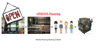
sPHENIX Directors Review Magnet: Cryogenics Roberto Than C-AD: Cryogenics August 2-4, 2017 BNL 1 sPHENIX Director's Review Aug 2-4, 2017
Magnet Coil Stored energy: 27 MJ@4600A; Quench: 14 MJ. Cooldown Thermal energy: 4.5K to 293K: 1.7 Giga-Joules Average Cooling power: 2 kW over 10 days, 3 kW over 7 days 4.5 K Load: 70W Design Operation: 4.5K Liquid supply @ 6.5 g/s. Excess flow, return as 2-phase flow on 4.5K Return line Thermal shield flow: 0.5 g/s Current lead flows: 2 x 0.25 g/s 2 sPHENIX Director's Review Aug 2-4, 2017
Requirements Provide cooling from RHIC main cryogenic system Hold Magnet at 4.5K Current leads cooling flows; Ramp with current Thermal Shield flow Handle Quench Local liquid helium inventory for magnet rampdown in the event of loss of 4.5K supply Controlled cooldown gradient of 40K or less Cooldown time: approx. 7-10 days Hold magnet at approximately 100K during summer shutdown 4.5K Test without RHIC Cryogenics Re-use existing solenoid valvebox with current leads and existing temperature instrumentation 3 sPHENIX Director's Review Aug 2-4, 2017
Technical Design Provide cooling from RHIC main cryogenic system Cooldown from 300K to 50K occurs during the RHIC collider;s 4 weeks 45K cooldown wave using 45K, 4bar flow. Budget 10 g/s. Design for 15 g/s. Controlled cooldown gradient of 40K or less No warm supply line to 1008 from RHIC cryo system [3000 ft required] 15 kW Heater or Heat Exchanger+3 kW heater using 45K gas from RHIC Mix warm and cold gas using heater. LN2 cooling using LN2 exchangers and 10 o clock-1010B compressor[available shutdown] Hold magnet at approximately 100K during summer shutdown LN2 supply with exchangers, helium circulation with a compressor at 10 o clock bldg. 1010B 4.5K Test without RHIC Cryogenics Cryo line connection with stinger to transfer from portable helium dewar Magnet rampdown in the event of loss of 4.5K supply 400 L local reservoir Thermal shield: Use 4.5 K vapor; Current leads cooling: Use 4.5K vapor Quench: Pressure controlled to protect return line. Excess will be handled by dump valve. 4 sPHENIX Director's Review Aug 2-4, 2017
Scope Cryogenic Transfer line system [WBS 1.8.3.1] Interface and isolation valves to RHIC Main Cryogenic Distribution ~160 FT Transferline bundle run from building 1008B into IP8 Hall Removable jumpers between Transferline bundle run and Interface Valvebox Interface Valvebox [1.8.3.1] Electric Heater, Cryo valves, LN2/GN2 heat exchangers, 400L Liquid Helium reservoir LN2 supply transfer line [500 FT] [1.8.3.2] From existing 1008 storage dewar to IP8 Hall Multi segment bayonetted line Warm Piping System [1.8.3.3] GN2 vent to outside of building [ 80 FT] Current leads cooling return flows & connection to WR (RHIC Warm Return) [200 FT] Controls Hardware, Software [1.8.3.4, 1.8.3.5] Utilities: Instrument Air [RHIC Cryo], Electrical: 480V, 120V. LN2 from 1008 LN2 storage dewar 5 sPHENIX Director's Review Aug 2-4, 2017
Cryogenic System Diagram External Portable LHE Dewar New LN2 Cryo Line New Helium Cryo Line System LN2, 6 bar Storage New Interface Valvebox S: 4.7K, 3.5BAR H: 60K, 12BAR LN2 Cooler U: 4.6K, 1.25BAR RHIC Distribution WR: 290K, 1.2 BAR 400L LHe 10 o clock location 18 g/s Compressor Current Leads Solenoid Cryostat SC SOLENOID Solenoid Valvebox THERMAL SHIELD 6 sPHENIX Director's Review Aug 2-4, 2017
Cryogenics System Layout Plan View Liquid Helium Transfer Line Elevation changes not visible in Plan view 7 sPHENIX Director's Review Aug 2-4, 2017
Cryogenics System Layout Plan View Liquid Nitrogen Transfer Line Elevation changes not visible in Plan view 8 sPHENIX Director's Review Aug 2-4, 2017
Layout of Cryogenic Equipment Buffer Dewar Solenoid Valve Box Filling Dewar 9 sPHENIX Director's Review Aug 2-4, 2017
Subsystem Collaborators & Support Key Personnel: Collider Accelerator Department [C-AD]: Cryogenics Group Roberto Than: Cryo Group Head for 10 years. Cryogenic process engineer. 27 years cryogenics experience. Paul Orfin: Project Engineer. 7+ years experience with Cryogenics group Tom Tallerico: Group leader Cryo Controls/Instrumentation, 17+ years in Cryogenics group, 35+ years experience in controls and instrumentation. Brian Van Kuik: Cryo Instrumentation engineer. 10+ years RHIC Main Control Room Operation Coordinator PLC and HMI programmer for cryo controls for sPHENIX solenoid low/high power test Cryo Group: Mechanical and electrical technicians with 20+ years cryogenic equipment and cryogenic instrumentation experience Robert Meier: Senior Designer. 15+ years designing for cryogenic group. Support and interface with: Paul Giannotti, Infrastructure sPHENIX Facilities and Experimental Support Group; C-AD Electrical Power Distribution Group; C-AD : Communcations and Electronic Support; C-AD Electrical Systems: Electrical Power Supplies Group; C-AD Controls systems: Front End Systems; C-AD Controls systems: Access Controls; BNL Central shops: Welding support 10 sPHENIX Director's Review Aug 2-4, 2017
Schedule and Schedule Drivers Engineering: Now 10/2017 Design/drawing package: 10/2017 4/2018 Float: 5/2018-8/2019 CD2/3b: 8/2019 RFP/RFQ: 8/2019 1/2020 Manufacturing: 1/2020 3/2021 Installation:3/2021 3/2022 No schedule drivers 11 sPHENIX Director's Review Aug 2-4, 2017
Cost and Cost Drivers WBS Subsystem Material Cost $ Conti- gency Total $ Labor $ Conti- gency Total $ 1.8.3 1.8.3.1 Cryogenic Transfer line system & Interface Valvebox 1,100 K 30% 1,430 K 440 K 30% 572 K 1.8.3.2 LN2 supply transfer line 233 K 30% 303 K 134 K 30% 174 K 1.8.3.3 Warm Piping System 65 K 30% 85 K 179 K 30% 233 K 1.8.3.4 Controls Hardware 126 K 30% 164 K 110 K 30% 143 K 1.8.3.5 Controls Software 128 K 30% 166 K TOTAL 1,524 K 1,981 K 991 K 1,288 K 12 sPHENIX Director's Review Aug 2-4, 2017
Basis of Estimate and Resource-Loaded Schedule Subsystem Basis of estimate Cryogenic Transfer line system & Interface Valvebox Based on previous cryogenic equipment procurement and engineering judgment LN2 supply transfer line Based on previous cryogenic equipment procurement and engineering judgment Warm Piping System Based on previous installation and materials procurement engineering judgment Controls Based on previous installation and materials procurement Existing Control Rack for low/high power test in bldg. 912. Expand I/O chassis for new equipment 13 sPHENIX Director's Review Aug 2-4, 2017
Status and Highlights Magnet High Power Test in building 912 Ready for reinstallation of cryogenic connection Control logic updated for high power test Cryo plant in 912 available after SRF cavity test 1008/IP8 Cryogenics Process Engineering: 80%. Remaining during design phase Mechanical Engineering: 30%. Remaining during design phase Design and drawing packages: Piping and Instrumentation Detail Diagrams to be completed. Start modeling and design: Oct 2017 14 sPHENIX Director's Review Aug 2-4, 2017
Issues and Concerns, Summary Design concept and engineering fairly mature, interfacing details to be finished during design and layout. Design & Drafting: Waiting for experienced cryo designer to free up. ~ Oct 2017 Schedule: Sufficient float between design completion and CD2/3b Experience with Low-power-test and high-power-test in bldg. 912 early on will be beneficial for cryo and power supply operations. Capability to cooldown and do a brief 4.5K test without RHIC cryo system will be engineered in, although not trivial. 15 sPHENIX Director's Review Aug 2-4, 2017