Overview of Traction Transformer Systems
Traction transformers play a crucial role in overhead traction systems by converting power supply to the required voltage for locomotives. The 25 kV single-phase system is widely used, with variations such as the 50 kV system for heavy haul applications. This article explores the evolution, suppliers, and operational aspects of traction transformer systems in railway networks.

Download Presentation

Please find below an Image/Link to download the presentation.
The content on the website is provided AS IS for your information and personal use only. It may not be sold, licensed, or shared on other websites without obtaining consent from the author.If you encounter any issues during the download, it is possible that the publisher has removed the file from their server.
You are allowed to download the files provided on this website for personal or commercial use, subject to the condition that they are used lawfully. All files are the property of their respective owners.
The content on the website is provided AS IS for your information and personal use only. It may not be sold, licensed, or shared on other websites without obtaining consent from the author.
E N D
Presentation Transcript
Traction Transformer PRESENTED BY PROF. VG PATEL VG PATEL
TRANSFORMER ENCYCLOPAEDIA TRACTION TRANSFORMER 25 kV Single Phase is the most preferred and universally accepted voltage standard for overhead traction system. Looking for any other voltage system, means every things has got to be developed namely Traction power supply system, Over Head Equipment, vehicle traction system etc. In order to increase OHE voltage, 2 25 kV system is developed so that at vehicle level, the voltage remains 25 kV. Some Railways have preferred for 50 kV system but the same is limited to heavy haul dedicated rail system in which the locomotive also remains confined in that territory only. VG PATEL Wednesday, March 12, 2025 2
TRANSFORMER ENCYCLOPAEDIA TRACTION TRANSFORMER There are not many suppliers of this traction system. Dedicated freight Corridor project in India thought meant for heavy haul, but the locomotive has to work in DFC and IR territory, therefore, 2x25kV power supply system is chosen. 25 kV Traction power system was designed, developed and demonstrated all over world by SNCF. Indian while completing electrification of HWH-Bardwan section of Eastern Railway decided to adopt 25 kV system in collaboration with SNCF and converted 3000V DC just when it was completed into 25 kV instead running it at 3000 V DC. VG PATEL Wednesday, March 12, 2025 3
TRANSFORMER ENCYCLOPAEDIA TRACTION TRANSFORMER The rolling stock procured from abroad was diverted for Mumbai Sub-urban system and used after conversion from 3000 V DC into 1500 V DC. 132 kV / 220 kV 3 phase supply is taken from State Utility and two phase (say U-V) are dropped at Traction Sub-station and for the purpose of load balancing V-W, VW and WU phase are dropped at subsequent TSSs. There are mainly five types of power supply arrangement so far prevailing over Indian Railway network. These developments are historical instead for any technical advantages. VG PATEL Wednesday, March 12, 2025 4
TRANSFORMER ENCYCLOPAEDIA TRACTION TRANSFORMER Power is purchased and paid at 25 kV from supply utility. Supply utility is responsible for owning, installation, operation, maintenance of 100/132/220 kV transmission line, grid substation up to 25 kV outgoing terminal. 25 kV feeder circuit breaker is controlled through SCADA by Traction Power Controller. This arrangement was adopted when IR was not having the resource and experience of handling HV equipment. Such substations were called GSS (Grid Sub-station) . It is similar to 1 above except that 25 kV circuit breakers are owned, installed, operated and maintained by the Railways. In this arrangement of operation by Railways and maintenance by State Utility has ended. VG PATEL Wednesday, March 12, 2025 5
TRANSFORMER ENCYCLOPAEDIA TRACTION TRANSFORMER IR observed that there is always delay in which the GSS were not getting ready and delaying the RE projects. Scheme was thus adopted to have power supply at 132/220 kV at TSS incoming and thereafter everything under the control of IR. These substations were called TSS (Traction Substation). For Tundla-Kanpur section of Allahabad Division, another scheme was adopted in which 132 kV transmission line is also owned by IR and 3 phase supply is taken at one point and two phase power is tapped at IR owned TSSs. This system benefited IR to save time on execution of transmission line work, complain from State Utility of power imbalance and helping IR of improving Load factor. This arrangement has helped IR at a later stage to take power supply directly from NTPC at better tariff and distribute on its network. VG PATEL Wednesday, March 12, 2025 6
TRANSFORMER ENCYCLOPAEDIA TRACTION TRANSFORMER In Bhusawal Division of Central Railway, Scott connected transformer used to take care of the issue of power imbalance generally complaint by State Utility in which 3 phase supply connection is taken and converted in to two phases by Scott connection transformer. The TSSs are owned by Railways. Power supply arrangement will take a new shape when evacuation of power supply from IR owned captive power plant at Nabinagar is synchronized to the grid. This is the subject of discussion at different forums of IR. VG PATEL Wednesday, March 12, 2025 7
TRANSFORMER ENCYCLOPAEDIA TRACTION TRANSFORMER Reliability of Traction Power Supply Reliability of traction power supply means to design redundancy in such a manner that at no instant there is discontinuity of power supply to traction vehicle for more than a tripping time plus the time take for isolation and feed extension. This is ensured by having power supply system to consist Traction Substation, Feeding Post, Sectioning and paralleling Post (SP or also called Neutral Section) and Sub-sectioning and Paralleling post (SSP) and Elementary section. Redundancies are designed at all stages ensuring availability of power supply on account of failure of supply from source or any other power supply equipment. VG PATEL Wednesday, March 12, 2025 8
TRANSFORMER ENCYCLOPAEDIA TRACTION TRANSFORMER Substation Special features for ensuring continuity of supply are summarized as follows: 132/220 kV supply is taken through double circuit 3 phase transmission line or drawing two phases from the nearby grid substation. If the grid substation is nearby, it is better to avail three phases. Advantage is to facilitate its usage for general supply. When general supply load is high, then the same can also be arranged by installing 132/33kV transformer at TSS. Railway Board has issued instruction to this effect to improve reliability of power supply for general purpose and avoidance of use of Diesel Generator set for emergency loads. Some other important points in this regard which can be helpful in decision making are . VG PATEL Wednesday, March 12, 2025 9
TRANSFORMER ENCYCLOPAEDIA TRACTION TRANSFORMER It is observed that failure of 132kV feeder is rare, therefore it is better to avoid expenditure for running duplicate feeder. This has been done in some cases. When there are two feeders, some of the Railways preferred for paralleling of two feeders to reduce transmission losses. This can be of use of the metering is at supply point. However there are instructions of Regulatory commission that the metering shall be provided at user point. There are some utility which asks for high load factor, say 35% DVC, which is difficult to achieve. The load factor of Railway feeder is generally 25% and therefore Railways had to pay heavy penalty. VG PATEL Wednesday, March 12, 2025 10
TRANSFORMER ENCYCLOPAEDIA TRACTION TRANSFORMER By having general supply feeder also at TSS, load factor can be improved and penalty payment can be converted into purpose full gain. Two sets of 132kV bus bars are provided. One is called main bus bar and the other maintenance or transfer bus bar. They are coupled through bus coupler circuit breaker. Isolators on both sides of circuit breakers and provision of transfer bus bar and bus coupler enable maintenance of circuit breakers and bus bars. Two numbers of Traction Transformer initially of 10/12.5 MVA and presently 30/32.5 MVA of 132- 220/25 kV single phase are provided at each Traction Substation. Wednesday, March 12, 2025 VG PATEL 11
TRANSFORMER ENCYCLOPAEDIA TRACTION TRANSFORMER For cost cutting, there was a phase during which only one transformer was provided at alternate TSSs. One number transformer is a hot stand bye. One leg of the transformer is solidly earthed and connected to rail which acts as a return conductor. In order to avoid unbalance, Scott connected transformer were also used in BSL division of Central Railway. An auxiliary transformer of 25kV/230V of 5/10/25 kVA rating is provided to meet the auxiliary load of lighting, control, fannage etc. at the substation. During initial state single phase connection was also given for oil filtration plant which was discontinued later on and mobile oil filtration plants working on DG sets were preferred. VG PATEL Wednesday, March 12, 2025 12
TRANSFORMER ENCYCLOPAEDIA TRACTION TRANSFORMER In order to improve power factor, series condenser with reactor is introduced on the return conductor at the secondary side of the transformer. Dynamic compensation is also provided at few of the Sub-station to take care of over compensation. There are some state utilities who levy penalty for over compensation but in many it has been over ruled by Regulatory Commission. The cost of Dynamic compen- sation is high and its own power consumption is so high throughout the day that it exceeds the benefit. Lightening arresters are provided at each control posts to protect every sub-section against voltages surges. Earth connection to lightening arrestor should have copper equivalent area of 50 sq.mm. VG PATEL Wednesday, March 12, 2025 13
TRANSFORMER ENCYCLOPAEDIA TRACTION TRANSFORMER It is often said that small is beautiful. But when it comes to technology, there are numerous other reasons that smaller is better. In many applications weight and space requirements directly influence productivity, research effort goes into footprint reduction. Some products, however, have largely resisted this tendency. The minimum size of a power transformer is essentially determined by the laws of physics, as the core must have certain dimensions to accommodate the magnetic field. and much VG PATEL Wednesday, March 12, 2025 14
TRANSFORMER ENCYCLOPAEDIA TRACTION TRANSFORMER One especially challenging application area for trans- formers is traction. The more space the transformer occupies, the less is available for passengers on the train. Its weight is also a factor in terms of permissible train axle load and additional energy needed to acce- lerate it. In terms of making this component smaller and lighter, the laws of physics fortunately provide some scope for improvement in the form of frequency. The higher this is, the smaller the required core. This principle is also found in low-power devices such as laptop chargers. But applying it to such large and heavy-duty items as traction transformers is not just about scaling. VG PATEL Wednesday, March 12, 2025 15
TRANSFORMER ENCYCLOPAEDIA TRACTION TRANSFORMER In the early days of electric railways, DC was the most common power supply. As it was at the time not feasible to step down DC voltages on-board the train, transmission between the substation and the train had to be at a low voltage (between 750 V and 3,000 V) so that it could be fed directly to the traction motors. The disadvantage of the low voltage was that it caused high conduction losses in the overhead line. VG PATEL Wednesday, March 12, 2025 16
TRANSFORMER ENCYCLOPAEDIA TRACTION TRANSFORMER Later, single-phase AC electrification using higher voltages was introduced (15 kV / 16.7 Hz and 25 kV / 50 Hz), reducing transmission losses. The penalty, however, was the large and heavy transformers that had to be carried on the train. For historical reasons, railways today use a multitude of different electrification systems, often based on what was state-of-the- art when electrification first began in a particular country or area. VG PATEL Wednesday, March 12, 2025 17
TRANSFORMER ENCYCLOPAEDIA TRACTION TRANSFORMER 2 Conversion path in a modern AC train VG PATEL Wednesday, March 12, 2025 18
TRANSFORMER ENCYCLOPAEDIA TRACTION TRANSFORMER 3 Conversion path using a medium-frequency transformer VG PATEL Wednesday, March 12, 2025 19
TRANSFORMER ENCYCLOPAEDIA TRACTION TRANSFORMER Medium-frequency transformers Medium-frequency transformers play three key roles. To start with, they provide galvanic isolation between the high voltage coming from the AC grid and the low voltage connecting the load. Their second key function is to provide suitable voltage adaptation for the 1.5 kV DC load voltage considering the 3.6 kV intermediate DC-link voltage level. The third key functionality is to help the IGBT (insulated-gate bipolar transistor) modules in the LLC resonant circuits to work in the soft switching mode. VG PATEL Wednesday, March 12, 2025 20
TRANSFORMER ENCYCLOPAEDIA TRACTION TRANSFORMER The railway electrification systems of Europe On traditional trains pulled by locomotives, the heavy transformer is not necessarily a disadvantage as it contributes to adhesion: The maximum force that the locomotive can apply to pull a train without losing adhesion on the rails is limited by the weight of the locomotive. In modern passenger trains, however, there is a tendency toward multiple-unit trains where the traction equipment is not concentrated in the locomotive but distributed along the length of the train in the same vehicles in which passengers travel. With the increased number of powered axles, adhesion is no longer a limiting factor for the train's acceleration, but the weight and size of the transformer remain a major constraint for train designers. VG PATEL Wednesday, March 12, 2025 21
TRANSFORMER ENCYCLOPAEDIA TRACTION TRANSFORMER An ideal train would thus combine the low weight and small equipment footprint of DC trains with the low transmission losses of high-voltage AC electrification. Essentially, the challenge lies in making the transformer lighter. Unfortunately, the basic size and weight of a transformer are limited by the laws of physics. Factors determining the minimum size of a transformer include the frequency and the power rating lower frequencies require larger transformers. A higher frequency transformer would permit weight savings as well as space savings. This is the power- electronic traction transformer (PETT). VG PATEL Wednesday, March 12, 2025 22
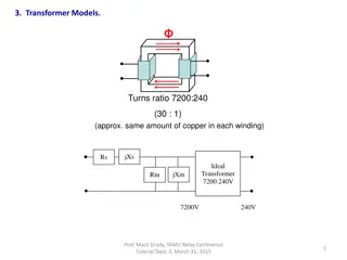
TRANSFORMER ENCYCLOPAEDIA TRACTION TRANSFORMER Principle of the PETT Current from the AC catenary (overhead line) flows through the primary windings of a low-frequency transformer (LFT) to the rail (which provides the return path). The reduced voltage available at the secondary windings of the transformer is fed into a four-quadrant line chopper converting it to DC-link voltage. An inverter converts this to variable-frequency and variable-voltage AC for the traction motors. Auxiliary supplies can also be fed from the DC link. Conversion path in a modern AC train To use a medium-frequency transformer (MFT), a frequency converter must be placed before the transformer. On the secondary side of the transformer, a rectifier converts this to the DC link voltage. VG PATEL Wednesday, March 12, 2025 23
TRANSFORMER ENCYCLOPAEDIA TRACTION TRANSFORMER Conversion frequency transformer One major challenge of this topology is that a converter must be located on the high-voltage side. With the present generation of semiconductor devices not being able to block the voltages used in AC railway electrification, a series connection is required. Rather than a mass series connection of semiconductors into single valves, the solution developed by ABB features a series cascade of converter modules on the high-voltage side, with the outputs connected in parallel on the DC side. This topology makes the solution scalable and provides scope for redundancy (the "M out of N" system). path using a medium- VG PATEL Wednesday, March 12, 2025 24
TRANSFORMER ENCYCLOPAEDIA TRACTION TRANSFORMER PETT with series cascade of converter modules on the primary side and outputs connected in parallel on the secondary side. The incoming AC from the catenary passes through a filter inductor before entering the first converter module. Each module of the converter consists of an active front end (AFE) block and a DC/DC converter block. The AFE block is essentially an H-bridge that regulates the charging of link capacitors. This topology also allows for active power factor control. VG PATEL Wednesday, March 12, 2025 25
TRANSFORMER ENCYCLOPAEDIA TRACTION TRANSFORMER Cascaded converters A further advantage of the cascade topology lies in the possibility of switching every module independently. This permits the switching patterns of the H-bridges to be interleaved. If they are interleaved evenly (i.e., offset by 360 degrees/N, where N is the number of levels), the grid side of the converter sees an apparent (equivalent) switching frequency that is 2 N times higher than the actual switching frequencies of the individual H-bridges. This high apparent switching frequency (combined with the larger number of intermediate voltage levels) leads to a lower harmonic distortion than is possible with conventional traction converters, and hence reduces the need for input filtering. VG PATEL Wednesday, March 12, 2025 26
TRANSFORMER ENCYCLOPAEDIA TRACTION TRANSFORMER Medium-frequency transformers Medium-frequency transformers play three key roles. To start with, they provide galvanic isolation between the high voltage coming from the AC grid and the low voltage connecting the load. Their second key function is to provide suitable voltage adaptation for the 1.5 kV DC load voltage considering the 3.6 kV intermediate DC-link voltage level. The third key functionality is to help the IGBT (insulated-gate bipolar transistor) modules in the LLC resonant circuits to work in the soft switching mode (described later). As overall size reduction increases the challenge from the dielectric point of view. This aspect has to be studied carefully. Wednesday, March 12, 2025 VG PATEL 27
TRANSFORMER ENCYCLOPAEDIA TRACTION TRANSFORMER In the present PETT demonstrator, all nine transformers share the same oil-filled tank, as does the line inductor and the start-up charger. LLC switching mode Each of the nine transformers is a part of the associated DC/DC converter. By using the transformer's leakage and magnetizing inductances and the external circuit's capacitors, a resonant LLC circuit is created (Lr, Lmand Cr). The advantages of an LLC circuit include: medium frequency VG PATEL Wednesday, March 12, 2025 28
TRANSFORMER ENCYCLOPAEDIA TRACTION TRANSFORMER Wide output-regulation range Reduction of switching losses on the primary side through zero voltage switching (ZVS) over the entire load range. Low turnoff current controlled by the design (not truly zero current switching, ZCS). Low-voltage stress and ZCS on the secondary side diode rectifier. Load-independent operation at resonant frequency. VG PATEL Wednesday, March 12, 2025 29
TRANSFORMER ENCYCLOPAEDIA TRACTION TRANSFORMER As an LLC circuit is based on the principle of resonance, variation of the switching frequency can be used to control the output voltage. However, in the present PETT implementation, this feature has not been used and the LLC resonant DC/ DC converter operates in the open loop with a fixed switching frequency of 1.75 kHz, which is below the resonant frequency. VG PATEL Wednesday, March 12, 2025 30
TRANSFORMER ENCYCLOPAEDIA TRACTION TRANSFORMER The control system The control targets can be summarized as: Maintaining sinusoidal input current Near-unity power factor Constant average DC-link voltage Grid harmonic rejection The hardware is ABB's AC 800PEC controller, a platform that permits the integration of fast and slow control functions. VG PATEL Wednesday, March 12, 2025 31
TRANSFORMER ENCYCLOPAEDIA TRACTION TRANSFORMER The PETT demonstrator on the SBB Ee 933 locomotive A pilot PETT installation is currently being tested on a type Ee 933 shunting locomotive. In early 2008, ABB initiated extensive research and engineering work on all subsystems. The PETT demonstrator development came to fruition in spring 2011 and subsequently underwent full electric testing in the laboratory before the pilot was taken into operation. The existing Ee 933 traction transformer and GTO rectifier were removed to provide space for the new PETT cubicle. Some mechanical adaptations and electronic interface rework was necessary to accommodate the PETT. VG PATEL Wednesday, March 12, 2025 32
TRANSFORMER ENCYCLOPAEDIA TRACTION TRANSFORMER The locomotive operates under the 15 kV/16.7 Hz railway grid. The pilot installation was completed in mid-2011, and homologation with the Swiss Federal Office for Transport (FOT) was achieved by the end of the year. The locomotive commenced shunting operation in February 2012 at the Geneva station. The PETT 8 has nine cascaded modules, of which only eight are essential for operations (the ninth is for redundancy). The unit has 1.2 MW nominal power and can supply 1.8 MW peak for short durations. The DC output voltage is 1.5 kV. The overall weight is 4,500 kg, including cooling. When comparing this with traction transformers of the same power rating, it should be noted that the PETT not only replaces the actual transformer but also the LV rectifier. Wednesday, March 12, 2025 VG PATEL 33
TRANSFORMER ENCYCLOPAEDIA TRACTION TRANSFORMER The main aim of this pilot is to study the feasibility of this optimization was an additional consideration. The power density (expressed in kVA/kg) of today's transformer and rectifier combinations is in the range of 0.2 to 0.35. The generation of future PETT under development will exceed this by a considerable margin, achieving values of 0.5 to 0.75. technology. Weight VG PATEL Wednesday, March 12, 2025 34
TRANSFORMER ENCYCLOPAEDIA TRACTION TRANSFORMER Further advantages include: Improved energy efficiency from AC input to DC output from 88 to 90 percent to more than 95 percent (today's average efficiency of 15 kV / 16.7 Hz standalone Traction transformer is in the range of 90 to 92 percent) Reduced EMC and harmonics Lower acoustic emissions All these factors make the PETT ideal for its stated goal of providing a small, lightweight but powerful converter solution that can be accommodated on the trains of tomorrow, and that is suited for operation in close proximity to passengers. VG PATEL Wednesday, March 12, 2025 35
TRANSFORMER ENCYCLOPAEDIA TRACTION TRANSFORMER The transformer of tomorrow !!! Although the PETT in this article is installed in a shunting locomotive, its real area of potential lies in multiple-unit trains for passenger service, such as commuter or high-speed trains. The PETT's compact size means it can easily be fitted under the floor of the train or on the roof, maximizing space available for passengers while reducing the train's power consumption. VG PATEL Wednesday, March 12, 2025 36
TRANSFORMER ENCYCLOPAEDIA OPEN FORUM Wednesday, March 12, 2025 37
TRANSFORMER ENCYCLOPAEDIA THANQ Wednesday, March 12, 2025 38