Explore the application of Pellegrini's cut-insertion theorem in feedback system design, including the use of block diagrams and passive networks. Discover how to address challenges and optimize feedback networks for optimal performance in electronic systems.
Please find below an Image/Link to download the presentation.
The content on the website is provided AS IS for your information and personal use only. It may not be sold, licensed, or shared on other websites without obtaining consent from the author. If you encounter any issues during the download, it is possible that the publisher has removed the file from their server.
You are allowed to download the files provided on this website for personal or commercial use, subject to the condition that they are used lawfully. All files are the property of their respective owners.
The content on the website is provided AS IS for your information and personal use only. It may not be sold, licensed, or shared on other websites without obtaining consent from the author.
E N D
Presentation Transcript
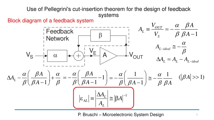
Use of Pellegrini's cut-insertion theorem for the design of feedback systems Block diagram of a feedback system a b b b OUT V V A = A Feedback Network L 1 A b S a b L ideal A VE VS VOUT a A = A A L ideal A L L a b b a b b a b a b A a b b A 1 A 1 b = ( 1) A + = 1 A L b b b 1 A 1 A 1 A A 1 b L A AL A L P. Bruschi Microelectronic System Design 1
Passive network: linear and reliable In a real electronic network: ? Feedback Network b VE VS VOUT a A Desired correspondence a b a b N N V V = out A A OL in Separation of feedback network and gain element (AMP) P. Bruschi Microelectronic System Design 2
Problems that prevent a direct correspondence between the electrical circuit and the simplified block diagram of a feedback system Loading effects of the feedback network on AMP Loading effect of the amplifier input impedance on the feedback network Direct signal path from the input signal VSand the output voltage through the feedback network (occurs if the amplifier has a non-zero output impedance). P. Bruschi Microelectronic System Design 3
Pellegrini's cut-insertion theorem A b a now are calculated taking into account loading effects takes into account the feed-forward path through the feedback network , , Z p v i a v v 1 1 Z ( ) p = b = = + b ; ; out v Z A r 1 A i v Z p i p out p = 0 v = = 0 0 v v s s s i v v v v is zero if the op-amp is unidirectional p = a = ; out v r s s s = = = 0 0 0 v v v p p p P. Bruschi Microelectronic System Design 4
Block diagram corresponding to the cut-insertion schematization a b b b v A a b = = out v A L 1 A s = = lim A b L ideal A A L a b b a b b v A = = + out v A L 1 A s = + lim A b A L Ideal feedback system P. Bruschi Microelectronic System Design 5
Problems when using the cut-inserion theorem for design purposes 1. I have to design the feedback network for three transfer functions (a b and ) instead of only two. 2. a and depend on the output impedance of the amplifier, Zo, which is a parameter that varies much and cannot be predicted reliably. 3. Only in the case that Zois much smaller than the typical impedances of the feedback network, we can design the network for a b and ) with port "O" short circuited ( =0). a b v = + out v s Configuration for a , P. Bruschi Microelectronic System Design 6
Example I want to design an inverting amplifier a b 0 0 b a a b= = = 5 5 L ideal A A passive network, including only resistors, capacitors and inductors (with no mutual inductance) cannot give transfer functions that are negative at dc. We need an amplifier provided of a inverting terminal P. Bruschi Microelectronic System Design 7
Cut insertion theorem with modified definition of a If AMP communicates with the feedback network only through the input and output ports (no intermediate signal paths) ...... b = b then * A new definition of a and b (renamed a* and b*) and: a b * v A v v = + out a b * * ; r r b b b 1 1 v A A v v s s o = = , 0 , 0 v v v v p o p s P. Bruschi Microelectronic System Design 8
Cut insertion theorem with modified definition of a The definition of a* is deeply different from that of a. Also the definition of b* is different from that of b. but the two values coincides in most practical cases. a* and b* are very similar to aNand bNthat are the functions for which we design the feedback network a b * Now is divided by the loop gain bA v A = + out b b b 1 1 v A A s a b a b * * v = = lim A b out v * s P. Bruschi Microelectronic System Design 9
Ideal transfer function and network functions a b a b * * v = = lim A b out v Feedback Network * O VO s Feedback Network O VO E Vr-ideal I VS Zp E I VS Vr = a + b r ideal V V V = a + b * * V V V N S N O r S O Z Z ( ) p = a + b V V V p a = a * r N S N O + Z Z N + Z Z a b a b * p e Z p e = N Z Ze * Z p p = a + b V V V p b = b * N r N S N O + + Z Z Z Z Vr-ideal N + Z Z p e p e p e P. Bruschi Microelectronic System Design 10
Finite gain error a b b * 1 A a b * = + = A L ideal A L * b 1 1 A a b b b b * A = + A 1 A A = + L 1 L 1 1 A A b 1 L ideal A L ideal A = A A L ideal A L L 1 A = + 1 e L a b b b b a b * * A r b L ideal A A L ideal A = + A L 1 1 A A From the Schwarz inequality: a b b b * A 1 = + 1 A + 1 e L b 1 1 A A r b A L ideal A P. Bruschi Microelectronic System Design 11
Conclusion a b a b * = = N L ideal A * N Feedback Network O VO E Vr-ideal I VS 1 Zo + 1 e r b A L ideal A Feedback Network Vout O Z Z + Zp E Zout I Vr b = b = b * in + = o Z A VOL A N Z Z Z in e o out P. Bruschi Microelectronic System Design 12