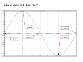
Phase Inversion Along Rabbit Ears: Wave Paths Exploration
Uncover the intricacies of phase inversion along wave paths in the study conducted by Han Yu, Bowen Guo, and Gerard Schuster at King Abdullah University of Science and Technology (KAUST). Delve into the objective, theory, numerical examples, and misfit objective function to better understand this innovative approach in seismic imaging.

Download Presentation

Please find below an Image/Link to download the presentation.
The content on the website is provided AS IS for your information and personal use only. It may not be sold, licensed, or shared on other websites without obtaining consent from the author.If you encounter any issues during the download, it is possible that the publisher has removed the file from their server.
You are allowed to download the files provided on this website for personal or commercial use, subject to the condition that they are used lawfully. All files are the property of their respective owners.
The content on the website is provided AS IS for your information and personal use only. It may not be sold, licensed, or shared on other websites without obtaining consent from the author.
E N D
Presentation Transcript
Phase Inversion Along Rabbit Ears (Wave Paths) Han Yu, Bowen Guo, Gerard Schuster King Abdullah University of Science and Technology (KAUST), Thuwal, Saudi Arabia Mar., 2014
Outline Objective Theory Numerical Examples Summary 2
Objective Tomogram: A good background velocity model for FWI and RTM Data: More Kinematics than Dynamics 3
Inversion along Wave Paths The earth model = background (??) + reflectivity (??) ? ? = ??? + ?? ? . Here, we focus on updating the background model (?+?)? = ?? (?)? ? ???? ? .(Xu et. al, 2012) ?? ? : step length ???? ? : stacks of the wave paths. 4
The Misfit Objective Function The goal is to better match: ????? (the observed data) with ?????? (the demigrated data) Previous methods: min | ????? ?????? | or max | ????? ?=??????? |(Shen et. al, 2013; Qin et. al 2013) Proposed method: Focus on the phase difference in ????? and ?????? . 5
A Two-Layered Example A simple two layered example: Updated Vel (FWI) FWI Gradient Wave Path Gradient Updated Vel (Wave Path) 6
Misfit and Work Flow Receiver side wave path: S0: ? ? = ?,??????|? ? ? ? ?(?|?) S1: ??? = ?,?? ?|? ?(?)? ? ? S2: ??? = ?,? ? ?|? ? ? ? 7
Misfit and Work Flow Source side wave path: S3: ??? = ?,?,?? ?|? ?(?) ? ? ? S4: ??? = ?? ? ? (?+?)? = ?? (?)? ? ?(???? S5: ?? + ???? ) 8
Phase Match How to calculate the ? ?|? ? ??????|? = ? ?|? ?(?)? ? ? ? ? ????? = ????????{??????} ? ???? = ???????{?????} Replacing ????? by ????, and estimate ? ?|? by ? = ? ????????{?????} ? ???????? ?????? (Sun et.al , 1993) 9
Data Match in Phase ? = ? ????????{?????} ? ????????{??????} ? = ???? ????? Data Comparison Spectrum Comparison 10
Numerical Example True Overthrust Tomogram Mesh size: 126 * 701 0 Grid spacing: 10 m Depth Z (km) Source: Ricker peaked at 5 Hz km/s Number of Shots: 88 1.2 3 5 1 7 Shot Spacing: 80 m A Smoothed Tomogram 0 Number of Receivers: 175 Depth Z (km) Receiver Spacing: 40 m Recording Length: 1.5 s Temporal Sampling : 1 ms 1.2 3 5 1 7 Distance X (km) 11
Inversion Results The Initial 1D Velocity Model FWI Inverted Tomogram 0 Depth Z (km) 1.2 3 5 3 5 1 7 1 7 Phase Inverted Tomogram along Wave Paths Conventional Wave Path Inverted Tomogram 0 Depth Z (km) 1.2 3 5 3 5 1 7 1 7 Distance X (km) Distance X (km) 12
Data Comparison Phase Matched Born CSG Regular Born CSG Finite Difference CSG Finite Difference CSG 0.5 0.5 Time (s) 1.0 1.0 1.5 1.5 100 100 50 150 50 150 Receiver Index Receiver Index 13
RTM Image Comparison Image Using True Tomogram Image Using True Tomogram Image Using 1D Model Image Using FWI Tomogram 0 Depth Z (km) 1.2 Image Using True Tomogram 3 5 3 5 Image Using True Tomogram 1 7 1 7 Image Using Phase Inverted Tomogram Image Using Phase & Amp Inverted Tomogram 0 Depth Z (km) 1.2 3 5 3 5 1 7 1 7 Distance X (km) Distance X (km) 14
Summary We focus on phase misfit more than amplitude for inversion along wavepaths. The inverted tomogram serves as an initial velocity for FWI. The data is not sensitive to the velocity perturbation. Future work: integrating this method with image domain inversion warping. & dynamic 15
Thank you! 16